Kenwood TK-481 Filter Changeout
The TK-481 does not need the existing receive filters centered at 938MHz changed out for use at 927MHz. These filters are rather broad banded, and little improvement can be gained by changing them but a good reason to change them out is mainly for the people in New England and other regions of the East Coast that still use the 12MHz repeater offsets.
The VCO in the TK-481 will do both 12MHz offset repeaters and 25MHz offset repeaters at the SAME time, or basically receive and talkaround (simplex) from 915MHz to 927MHz- something very few radios can do! The radio requires no modification to the VCO to do this but will require, for optimum sensitivity, that the receive filters be changed. Unlike the TK-981 the TK-481 handheld receive filters are not easy to change. You must be very careful doing this as there is not a lot of room for error due to the tight and compact nature of the radio being a handheld.
When the filters are changed out you can expect to see a handheld that has a 0.17 to 0.19uV for 12dB SINAD receiver from 915 to 928MHz!
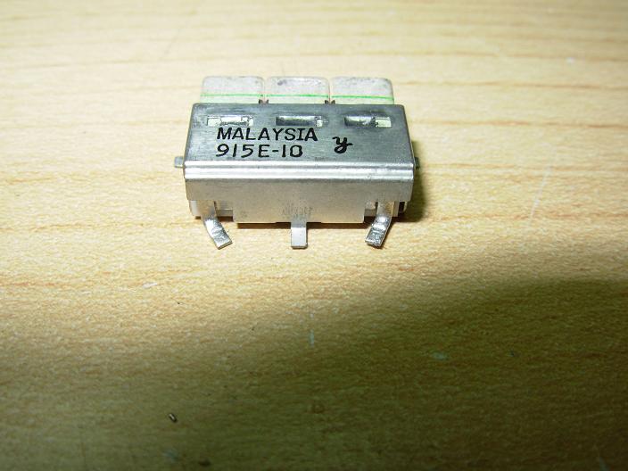
The front end of the TK-481 contains two 938MHz centered SMD filters. One filter is a 3 Pole unit- which is the exact same filter found in the TK-981, the other receive filter is a 2 pole unit which is unique to the TK-481. They are easy to remove, but require full focus when doing so and full attention to the surrounding area of the radio to insure that you do not damage any of the surrounding parts, as it's VERY easy to do. I have changed them out using a hot air SMD re-work station, as you can remove the filters entirely with no-damage to the traces on the board in around 1 to 2 minutes. The filters are a lot more difficult to remove using a normal soldering iron and I would NOT recommend this be done on the TK-481 due to the tight proximity of surrounding parts.
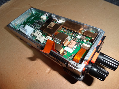
Pictured below is step by step disassembly as well as removal of the TK-481 receive filters using my Hakko 850 Hot Air station.
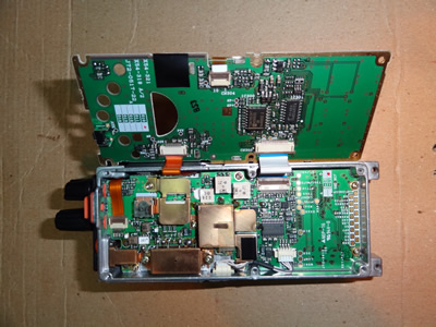
- You will need to disassemble your TK-481 by removing the antenna, battery, mic/program port side cover, and then removing the 2 screws that hold the chassis to the front panel. The front silicone keypad and speaker will need to be removed from the front of the radio and set aside.
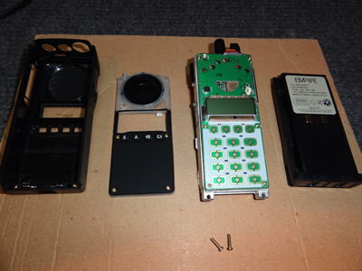
- The next step is to remove the 6 screws that hold the front panel to the body of the radio. After the front panel screws are removed you must now unplug the 2 ribbon cables that connect to the main chassis- be VERY careful doing this as the connectors are easy to break if you are not careful with them.
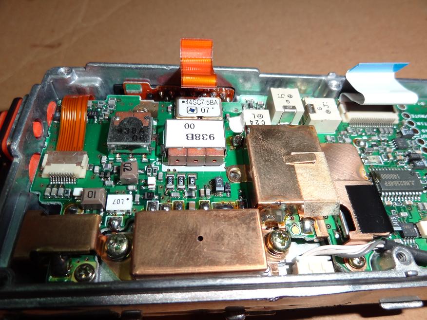
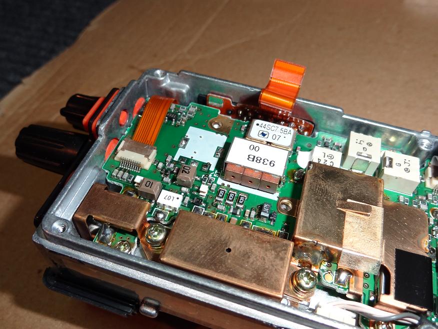
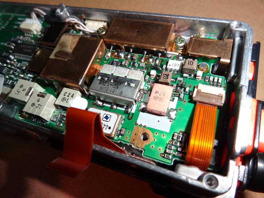
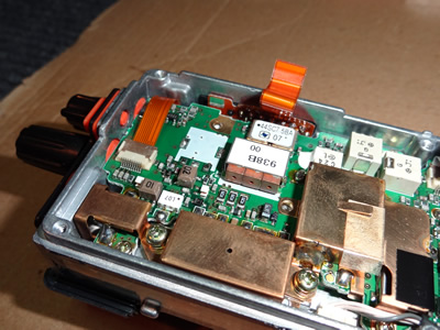
- We can now remove the RF shield that covers both the 2 and 3 pole receive filters. We will be re-using the RF shield so set it aside in a safe spot. From this point we can see how many different components there are on the main board to damage or destroy if we are not careful in our removal of the original filters- in particular the area around the 2 pole SMD filter.
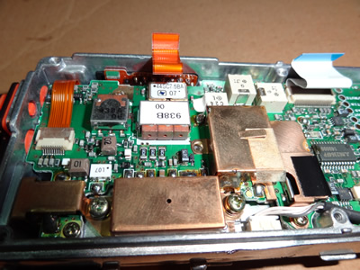
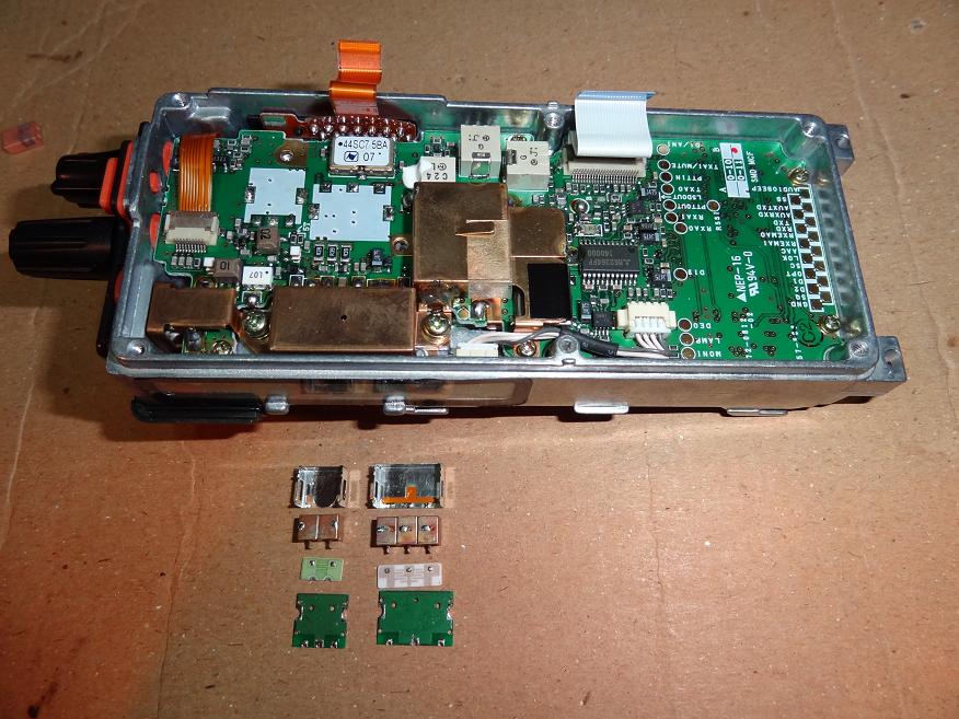
- We can now remove the 2 pole SMD receive filter. We want to be extremely careful at this step that the SMD inductors/capacitors/resistors/etc. are not damaged at this point because it's very easy to do so! On your hot air SMD re-work station make sure you dial back the air flow and never point the nozzle toward the inside of the radio as you will heat up and blow the SMD components off the board. Be sure to remove the SMD 2 pole filter piece-by-piece, do NOT try and remove the entire component at once! Once removed, let the area cool for a few minutes before moving on to the 3 pole SMD filter.
- You can now remove the 3 pole SMD filter. This filter comes out easier than the 2 pole filter so at this point it gets a little more relaxing of a task.
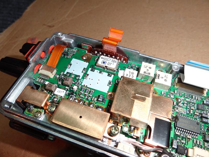
- After the 3 pole filter has been removed clean the area with Isopropyl Alcohol of 90% or use flux remover on a Q-tip to remove any residue.

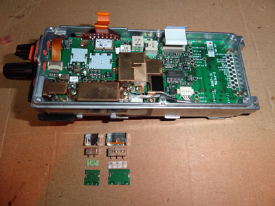
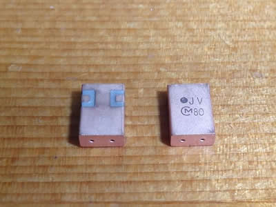
- The 3 pole filter will be changed out with a 915MHz centered, 26MHz Bandwidth, Toko 4DFB-915E-10 SMD Filter- which are almost a drop in replacement. The Toko 4DFB-915E-10 filter will require that you bend the input and output pins slightly so that they fit properly. Also ensure that you ground the ground tabs on either side of the filter by scraping the coating off of the board and soldering the filter ground pins to the board. Proper grounding of these filters, and all band pass filters in general, has a big impact on their proper function.

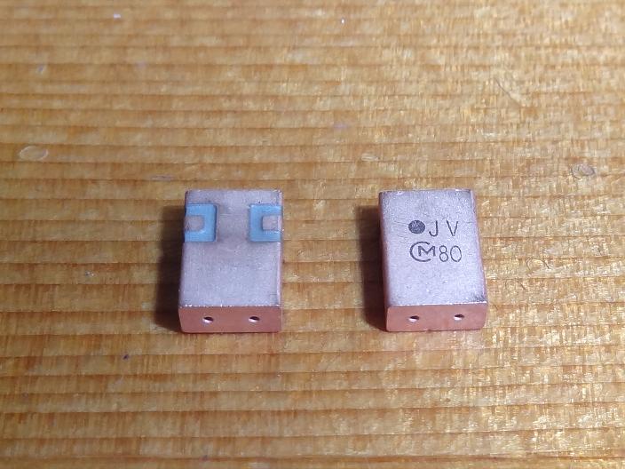
- The 2 pole SMD filter that I have used with great success is the Murata DFC2R915P026HHE which is a 2 pole, SMD, 915MHz centered, with a total bandwidth of 26MHz filter. These filters have terminals on either side of the filter and require VERY careful placement and positioning on the board so that the input/output terminals line up and that the body of the filter does not contact the SMD components towards the inside of the radio. It's a good idea to place the filter on the board and line up everything- and inspect that the body of the filter is not contacting or grounding out any components to terminals on the board.
There is also a 2 pole SMD 915MHz 26MHz Bandwidth Toko filter that is identical to the 3 pole filter that is almost a drop in replacement to the existing 2 pole. This filter is very hard to find, but if you have one then it makes filter change out a breeze compared to using the 2 pole Murata SMD filter.
- The finished installation should look neat and clean with no stray solder anywhere on the board. You also will want to check the surrounding areas around the filters to ensure that nothing was damaged or knocked loose. It is very important that the body of each filter be soldered to ground and well grounded at that. You will need to lightly scrape away the board coating and ground both the 2 and 3 pole filters to the main board.

- It is now time to start reassembling the radio. It is critical that the RF shield that covers the 2 and 3 pole receive filters be reinstalled. You may need to slightly bend or re-form the shield so that it properly grounds the 2 pole filter. Make sure that the filter shield does not stick up where it can contact the underside of the front panel when it is reinstalled- or better yet, place a small piece of electrical tape over the top of the copper filter shield so that the front panel cannot contact the copper shield when it is secured to the main chassis with the 6 securing screws. It is also important to be very careful when reinstalling the front panel and connecting the 2 ribbon cables to the main chassis.
- Now that the radio is reassembled you are finished at this point. If you find that the receiver is worse than when you started then open the radio back up and check all areas around the input/output pins of the filters, also check to ensure that no part of the filter body is touching any components in the radio other than the ground plane of the board of which it is soldered to. There are no adjustments to make to the radio at this point either, but it would be good practice to perform a full alignment on the radio using a service monitor. The most important thing at this point is to enjoy your new highly sensitive receiver!