Kenwood TKR-901 Repeater
The TKR-901 was a complete commercial repeater that was dip-switch programmable and had an RF output of 250mW. This repeater was dumb, meaning it required an external LTR-Trunking controller to be functional. For years the ham community had shown interest in getting this unit to work on the amateur radio band, as it was an "all-in-one" solution to using a pair of mobile radios and the TKR-901 showed up on the used market with no use beyond the commercial spectrum; that is until now.
The original TKR-901 uses a 42-pin NEC uPD75008CU microcontroller IC in the RX and TX modules inside. These microcontrollers are difficult to remove and require the use of a NEC programmer. To allow the masses to easily program the repeater for ham use required something simple and obtainable; the Raspberry Pi-Zero W. Thanks to Neil Reasoner, KB5ERY (SK) in April of 2014, the wait to use these repeaters in the 900MHz amateur radio band was over. Neal after a little experimentation wrote a simple program that runs on the Raspberry Pi-Zero W that will take the RX and TX data and on the fly change it so that the TKR-901 will RX and TX on 902.xxxx/927.xxxxMHz. The original TKR-901 without the use of the Raspberry Pi-Zero W uses thumbwheel switches to set the RX and TX frequencies, the Pi-Zero W does away with these thumbwheel switches altogether.
Presented below is information pertaining to modifying the TKR-901 repeater for ham use. The TKR-901 will use a Raspberry Pi-Zero W to change PLL data on the fly so that the repeater will RX at 902.xxxxMHz and TX at 927.xxxxMHz (including odd splits).
Thanks and credit goes to Graham Warrington, VE3WGW who performed a modification to his TKR-901 and captured all the details of the modifications needed. The below images are Graham's and not my own. If you find any mistakes, have pictures or something to add, etc...PLEASE contact me and I will add or correct as needed.
You will need the following Tools:
- 40-50 Watt Pencil Tip Soldering Iron with Solder Wick
- Hot Air Rework station is Optional- Makes the job easier!
- Digital Voltmeter
- Service Monitor/Signal Generator
- Phillips Head Screwdriver
- X-ACTO Knife
You will need the following Parts:
- One Raspberry Pi-Zero W or WH Model (external monitor/keyboard)
- Raspberry Pi-Zero code from "Downloads" section of this website
- 18-20 AWG wire (wire colors of choice)
- 915MHz 2-pole through hole Toko or Murata Receive Filter
CREDITS on this Project:
- Neal Reasoner, KB5ERY (SK), Cracked the Kenwood TKR-901 for amateur radio use and wrote the Pi-Zero Code
- Graham Warrington, VE3WGW, provided pictures, notes, as well as adaptation of Pi-Zero code to the newer Raspberry Pi-Zero W.
Step by Step Conversion of the TKR-901
- Disassemble the TKR-901 by removing the top and bottom covers.
- Using the service manual to program the RX and TX frequencies to your choice for testing to ensure the repeater is functional. The RX front end is tunable and depending on what frequencies you program you will need to tune L2 and L4.
- Power the TKR-901 up and using your service monitor test RX and TX- ensure the TX is on frequency and the power output meets specifications, power output can be adjusted using VR101. Test the RX and ensure the unit has good sensitivity.
The RX should be about 0.20 uv and TX about 250 mW output. Take note of the frequencies as you will need them later for alignment.
- If the LED's on the front of the repeater are flashing that means the VCO’s are out of lock. You will need to adjust the VCO voltage (L209).
- If the unit is operating then it is safe to say it will work, if not repair before you proceed.
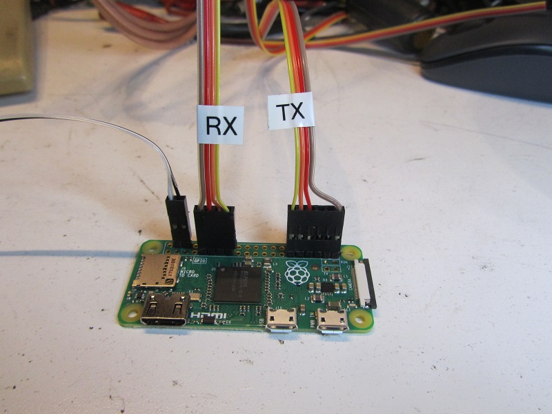
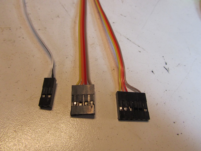
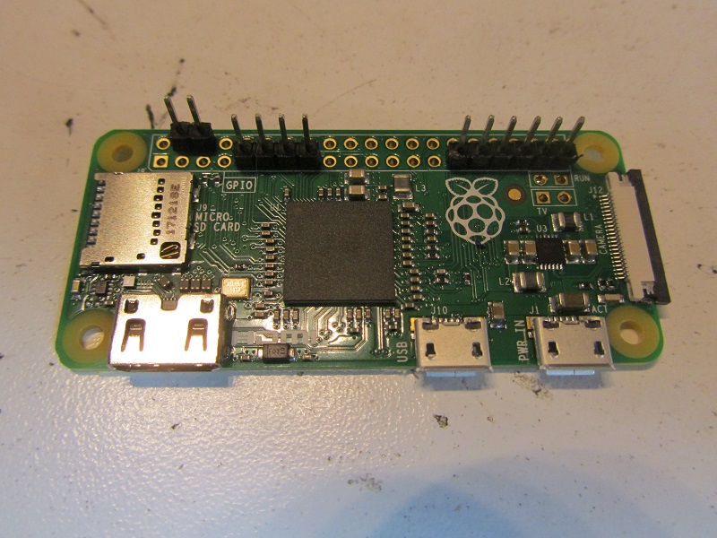
- You will need to get your wiring from the RX and TX boards to the Raspberry Pi-Zero W. Ribbon cable and headers were used to interface the GPIO on the Pi-Zero W to the PLL circuits on the RX and TX units as pictured. The 4-pin connector was used to interface to the RX and the 6-pin connector was used for TX.
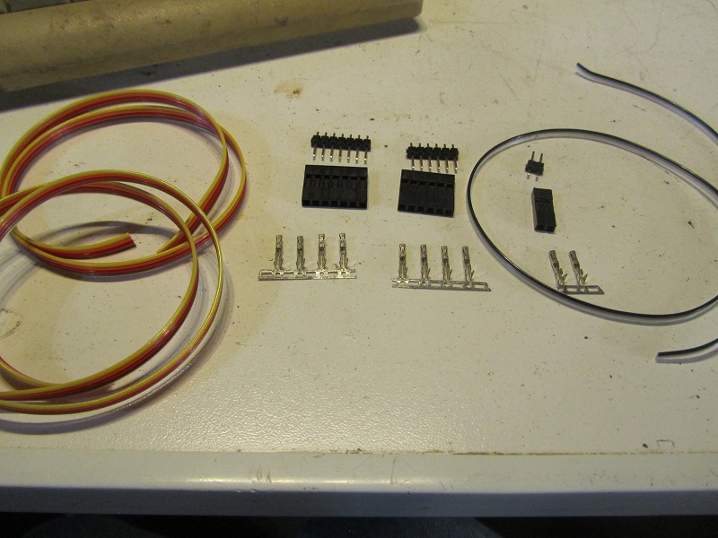
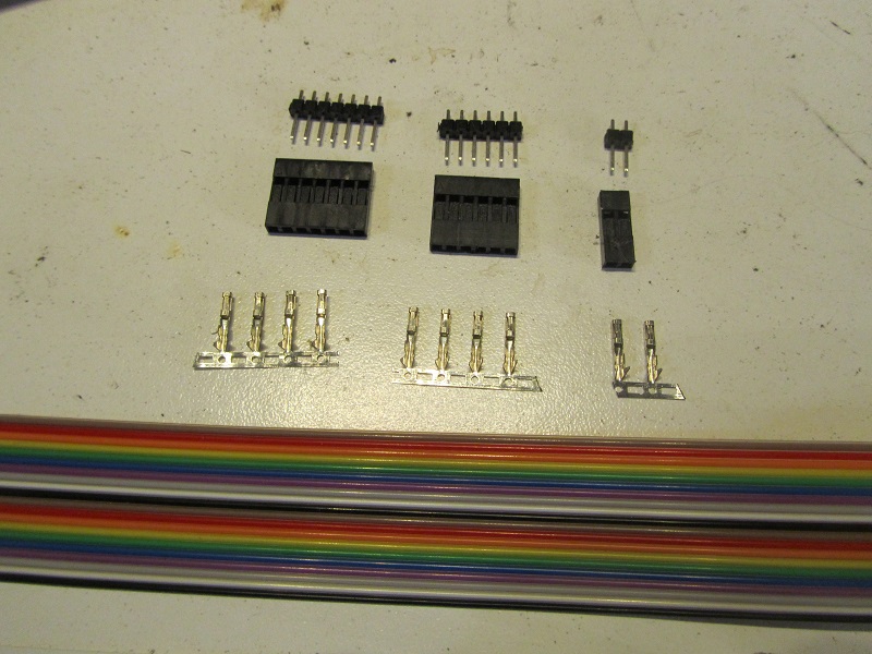
- If so desired at this point you can populate the Raspberry Pi-Zero W with header connectors to make wiring connections easier.
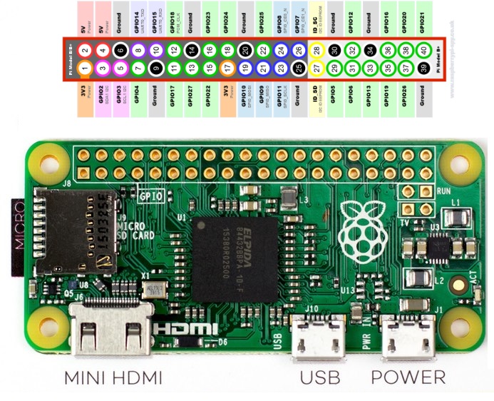
- Power connections using a 2 pin header will populate pins 4 and 6
- RX connections using a 4 pin header will populate pins 9, 11, 13, and 15
- TX connections using a 6 pin header will populate pins 29, 31, 33, 35, 37, and 39- please note that NO wires will be connected to pins 35 and 37!
RX Modifications
- First, we will modifiy the RX by removing the top and bottom covers from the RX unit; if you haven't already removed them. On the bottom of the RX unit remove R245, R247, and R248 which are loacted near IC203 the 42-pin NEC uPD75008CU microcontroller IC. These 3 resistors are for the PLL circuit; R245 is LE from Pin 22 of IC203, R247 is Data from Pin 24 of IC203, and R248 is Clock from Pin 25. By removing these resistors we remove IC203 from controlling the PLL for our RX frequency.
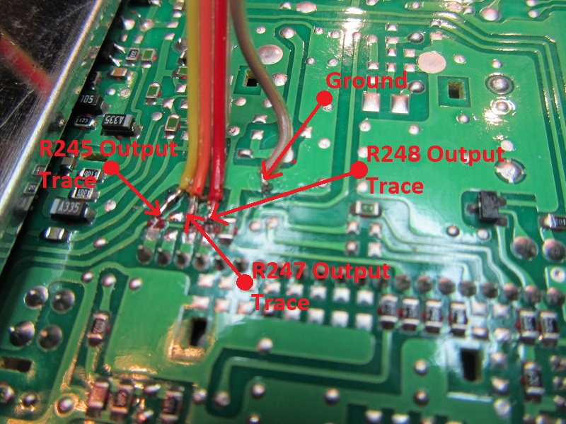
Connect about a foot long piece or therabouts (4 wires) to the output of the 3 pads that R245/R247/R248 were across- NOT to the pad of the resistor that IC203 is connected to!
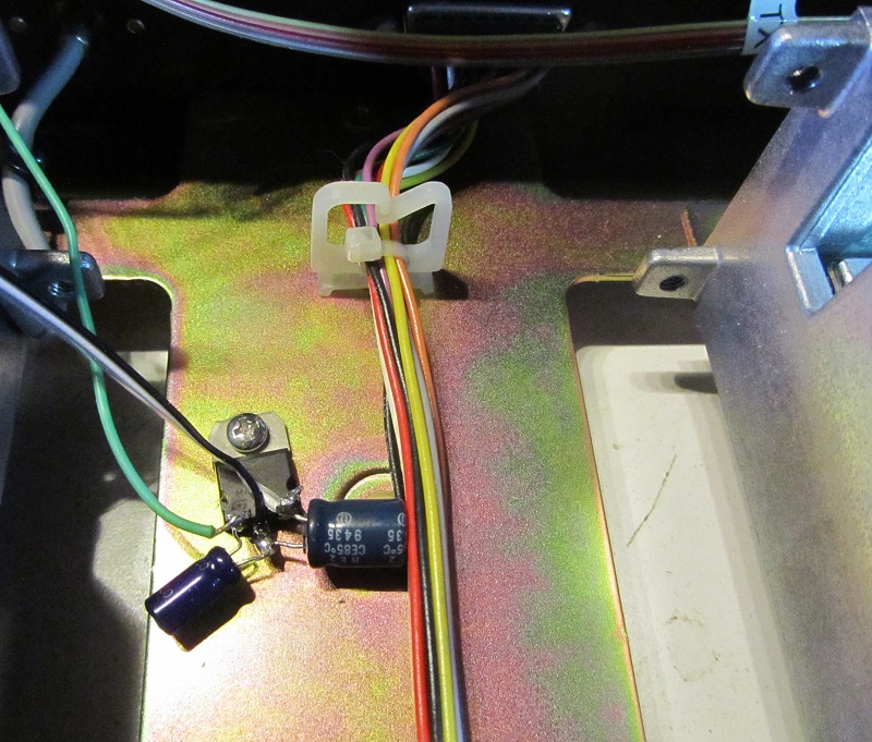
Shown below the YELLOW wire goes to the output of R245, the ORANGE wire goes to the output of R247, and the RED wire goes to the output of R248 as shown in the photo. The BROWN wire was utilized for ground.
TX Modifications
- Next we will modifiy the TX by removing the top and bottom covers from the TX unit; if you haven't already removed them. On the bottom of the TX unit remove R246, R247, and R248 which are loacted near IC203 the 42-pin NEC uPD75008CU microcontroller IC. These 3 resistors are for the PLL circuit; R246 is LE from Pin 23 of IC203, R247 is Data from Pin 24 of IC203, and R248 is Clock from Pin 25. By removing these resistors we remove IC203 from controlling the PLL for our TX frequency.
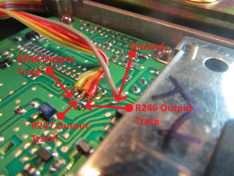
Connect about a foot long piece or therabouts (4 wires) to the output of the 3 pads that R246/R247/R248 were across- NOT to the pad of the resistor that IC203 is connected to!
The RED wire goes to the output of R246, the ORANGE wire goes to the output of R247, and the YELLOW wire goes to the output of R248 as shown in the photo. The brown wire was utilized for ground.
- We now need to be able to power the Raspberry Pi-Zero W which can be done very easily using a 7805 Voltage regulator with power to the reguator being supplied by the output of the supply fuse for the repeater itself.
- The terminated end from the RX unit of the ribbon cable goes to the Raspberry Pi-Zero W. Pins 9, 11, 13, 15 on your Raspberry Pi-Zero W will connect as follows:
Raspberry Pi-Zero W (GPIO Ground) Pin 9- BROWN; Ground on TKR-901 for RX
Raspberry Pi-Zero W (GPIO 17) Pin 11- RED; R248 on TKR-901 for RX
Raspberry Pi-Zero W (GPIO 27) Pin 13- ORANGE; R247 on TKR-901 for RX
Raspberry Pi-Zero W (GPIO 22) Pin 15- YELLOW; R245 on TKR-901 for RX
- The terminated end from the TX unit of the ribbon cable goes to the Raspberry Pi-Zero W. Pins 29, 31, 33, 39 (pins 35 and 37 are NOT used!) on your Raspberry Pi-Zero W will connect as follows:
Raspberry Pi-Zero W (GPIO 5) Pin 29- YELLOW; R248 on TKR-901 for TX
Raspberry Pi-Zero W (GPIO 6) Pin 31- ORANGE; R247 on TKR-901 for TX
Raspberry Pi-Zero W (GPIO 13) Pin 33- RED; R246 pad on TKR-901 for TX
Raspberry Pi-Zero W (GPIO Ground) Pin 39- BROWN; Ground on TKR-901 for TX
- The terminated end of the output of the 5V reguator power supply to the Raspberry Pi-Zero W will connect as follows:
Raspberry Pi-Zero W (GPIO Ground) Pin 6
Raspberry Pi-Zero W (GPIO +5V) Pin 4
- Your completed connections will look like the following picture.