TK-981 Tips and Modification
TK-981 KPG-49D Password Protected Radio Overwrite Bypass
The Kenwood TK-981 has a feature in the programming software, KPG-49D, that allows the .DAT file programmed in the radio to have a read protection password. This password protection only protects the file from being read from the radio, you can simply overwrite the file in the radio without issue (there is no write password). To read a password protected TK-981 perform the following steps:
- Start KPG-49D (Version 4.xx) and read from the password protected radio
- Go to "PROGRAM" and "READ DATA FROM RADIO" and read the radio as you would normally.
- Click on "READ".
- When the popup window for the password comes up you will need to press and hold the control (CTRL) key while typing the word "system" (no quotes), while still holding the CTRL key click "Ok" or press enter
- The software will now read the radio and you are all set!
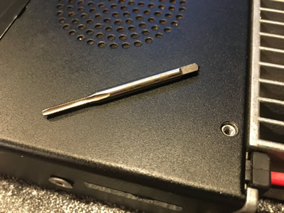
TK-981 Top/Bottom Cabinet Screw Thread Repair
The Kenwood TK-981 has four M2.6 raised oval countersunk screws that hold the top and bottom cabinets onto the chassis of the radio. Your chassis threads may be damaged and in need of repair, fear not, as this is very easy to do and relatively cheap. The tap size you will need is 2.6mm x 0.45mm thread pitch starter tap (finishing/bottoming tap optional). This tap size is not common and can usually only be procured via online resources. If there is a broken off cabinet screw in the chassis of your radio you can drill it out rather easily using a 1/16" drill bit, be sure to use a center punch so that your drill bit doesn't drift and stays on center. When drilling or using a tap to repair the chassis threads use caution and ensure that no metal shavings migrate onto the radio PCB (tape or mask off areas inside).

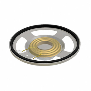
TK-981 Cheaper Replacement Speaker
This Kenwood TK-981 Tip is courtesy of Brad, KB9BPF, who was kind enough to share this with me. If you have a Kenwood TK-981 that is missing the internal speaker and do not want to spend the amount that Kenwood wants for an OEM speaker, Digikey has got you covered. You will need to have on hand 24-28AWG stranded wire (red and black to distinguish polarity). You will also need 1/4" foam of some sort which sits under the speaker magnet and is a doughnut shape. To assemble the CN6 connector will require small needle nose pliers and a steady hand (they are quite small). Listed below are the parts needed:
PUI Audio AS05708MR-R Speaker Datasheet
Non-OEM Replacement Speaker, PUI Audio, Digikey Part Number: 668-1299-ND
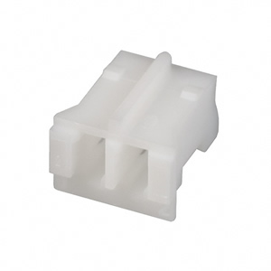
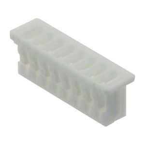
CN6 2-Pin Connector, JST, Digikey Part Number: 455-1165-ND
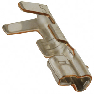
CN6 Connector Pins, JST, Digikey Part Number: 455-2148-1-ND
TK-981 MC-59 to KMC-32 Keypad Conversion
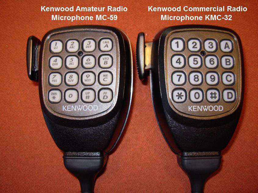
The Kenwood MC-59 DTMF microphone is the amateur radio version of the commercial Kenwood KMC-32 DTMF microphone. If you have a MC-59 DTMF mic and would like to convert the keypad to the KMC-32 DTMF keypad the conversion is quick and painless! Pictured below on the left side of the picture is the amateur radio Kenwood MC-59 DTMF mic, on the right side is the commercial radio Kenwood KMC-32- if you want the keypad of the MC-59 to look like that of the KMC-32 then the KMC-32 Silicone button keypad can be purchased from East Coast Transistor or Pacific Coast Parts; the part number is K29-5370-03.
TK-981 Received Signal Strength Indication (RSSI) Firmware
Sometime in 2010 special amateur radio edited firmware, NOT released by Kenwood (i.e. don't ask them about it!), surfaced allowing RSSI readout on the display of the Version 2 TK-981 and TK-481. This RSSI firmware was based off of Version 2, revision 18, checksum "E613" firmware. The modified version 2 RSSI firmware, checksum "7FB8", allows an arbitrary number between ~30 and 140 to be displayed on the upper left side of the display of the radio. These numbers are based off of how strong or weak a signal is into the radio's receiver; for example a weak signal would read 45 or thereabouts and a strong full quieting signal would read 130. The firmware has no other special features other then RSSI readout; some have referred to this firmware as "special ham firmware", there's not much special about this firmware other than it has been edited to allow the RSSI feature. This firmware is NOT for use in LMR commercial service.
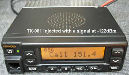
Pictured below is a Version 2 TK-981 being injected with a signal on 927.5000MHz at -122dBm; the display reads "056". An RF signal at -122dBm (0.18uV) would be very weak/noisy and would be just breaking squelch on the receiver.
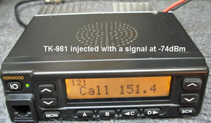
Pictured below is a Version 2 TK-981 being injected with a signal on 927.5000MHz at -74dBm; the display reads "121". An RF signal at -74dBm (45uV) would be very strong and would be very close to, but not completely, full quieting into the receiver.
The TK-981 has 2 pads on the top and bottom side of the RF board near the front panel display ribbon connector. The RSSI pad when connected to a VOM will give a DC voltage from ~0.600 to 2.8Vdc corresponding to a RF signal strength to the receiver. It should be mentioned that these pads always function regardless of the firmware in your radio. Testing the RSSI firmware feature with a TK-981 radio on the bench by injecting the unit with an RF signal from -124 to -50dBm and plotting the RSSI readout and RSSI test pad Vdc will give us an idea of how linear the response is of this feature. Test equipment used was an IFR 1200 Super S service monitor (NIST calibrated) and a Fluke 87 III VOM (NIST calibrated). One thing that is very important to remember is that every radio will be slightly different; in other words there is no universal chart that corresponds RF signal strength, in dBm or uV, to a displayed RSSI readout- therefore if you were to take the charts shown below and compare them to your TK-981 by injecting the same RF signal levels into your radio, the RSSI value displayed would be different from the ones shown here- it's an arbitrary number; unless you make your own dBm to displayed RSSI value chart for your radio. However, this feature is still handy if you use a beam antenna and rotor so that you can aim the antenna in the direction of the RF signal you are trying to receive, but other than that use, the displayed RSSI number is more of a novelty.
Pictured below are the results of bench testing the TK-981 RSSI firmware feature.
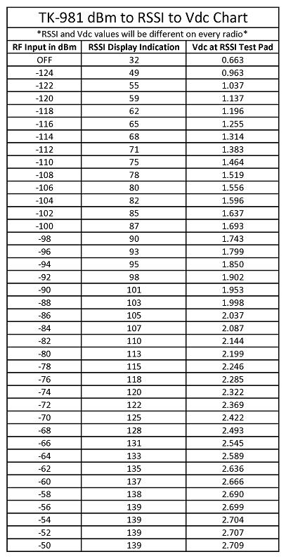
This chart is downloadable in PDF TK-981 RSSI Example Chart
A plot of signal strength, in dBm, into the receiver verses the displayed RSSI value is pictured below.
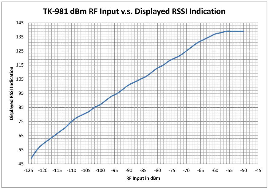
This plot is downloadable in PDF TK-981 dBm vs RSSI Displayed
A plot of signal strength, in dBm, into the receiver verses the voltage at the RSSI test pads on the main RF board is pictured below.
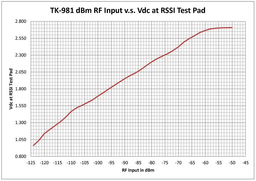
This plot is downloadable in PDF TK-981 dBm vs RSSI Vdc
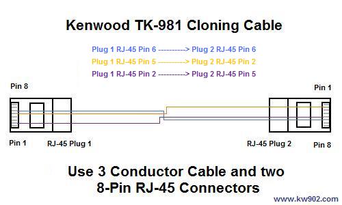
TK-981 Cloning Cable
If you want to use the clone feature that the TK-981 is capable of its rather easy to make your own cloning cable. To make a cloning cable you will need a small length of 3 conductor cable and two 8-Pin RJ-45 connectors. The clone feature will copy the radio programming DAT file in one radio to another radio; the tuning data is NOT copied. If you would prefer to purchase a cloning cable rather than build one they are no longer available from East Coast Transistor or Pacific Coast Parts. The diagram below will aid you in making a clone cable. Please note that the view shown is looking down, with the pin side facing up, on each RJ-45 connector.
To clone a Kenwood TK-981 to another TK-981:
- One TK-981 (the MASTER radio) will be used to transfer data to a second TK-981 (the SLAVE radio). The MASTER radio must have the Clone feature enabled in the DAT file, the SLAVE radio does not need this feature enabled. To enable the Clone feature in the MASTER radio DAT file use KPG-49D and go to the "Edit" menu and then select "Optional Features" from there click on the "Optional Features 2" tab and under the "Mode" section select the "Clone" checkbox, write this DAT file back to the MASTER radio.
- On the radio you are going to be CLONING FROM (this is the MASTER radio that has Cloning enabled in step 1 above) power on the radio with the "C" button held down for 5 seconds, then release, the display will read "CLONE MODE"- this is the MASTER radio.
- On the radio you are going to be CLONING TO (the SLAVE radio) power on the radio as you would normally.
- Connect the cloning cable between the MASTER and SLAVE radio.
- Press the "SCN" button on the MASTER radio to start the clone process.
- The SLAVE radio will display "PROGRAM" on the display.
- When data transfer is complete the MASTER radio will display "END" on the display and the SLAVE radio will power off and back on and be ready for use, the MASTER radio will need to be manually powered off and back on again to be ready for use.
- Congratulations, you have now copied programming from one radio to another!
Kenwood KCT-19 Accessory Connector Cable DIY for the TK-981
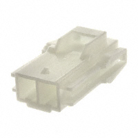
If you have been trying to find some KCT-19 accessory connector cables to simply bring internal radio connections out to the back of the radio and had no luck finding them, fear not. Below is information that will allow you to build your own KCT-19's at very little cost, take note that CN1 thru CN6 exist on the TK-981. The connectors and pins are made by two different manufacturers; Molex Japan and JST. Molex Japan makes the connectors and pins used on CN1, CN2, and CN4 which is part of their PicoBlade Series. JST makes the connectors used on CN3, CN5, and CN6 which are part of their PH series, they can be purchased from DigiKey.
Molex PicoBlade Series Connector Datasheets (CN1, CN2, and CN4)
JST PH Series Connector Datasheet (CN3, CN5, and CN6)
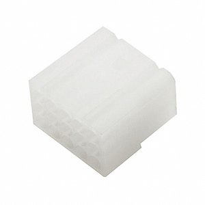
CN1 8-Pin Connector, Molex Japan, Digikey Part Number: WM1726-ND
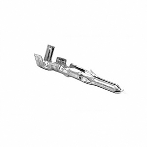
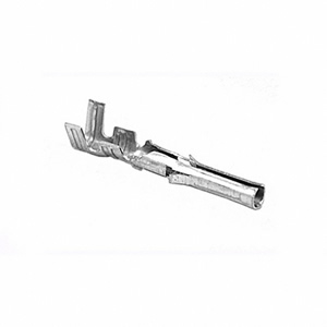
CN1 Connector Pins, Molex Japan, Digikey Part Number: WM1142CT-ND

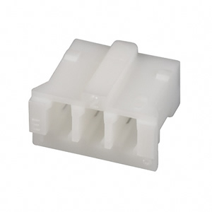
CN2 and CN4 3-Pin Connector, Molex Japan, Digikey Part Number: WM1721-ND
CN2 and CN4 Connector Pins, Molex Japan, Digikey Part Number: WM1142CT-ND
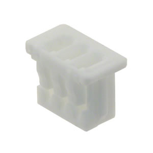
CN3 and CN5 3-Pin Connector, JST, Digikey Part Number: 455-1126-ND
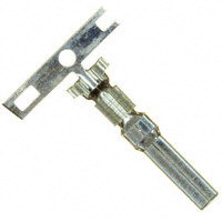
CN3, CN5, and CN6 Connector Pins, JST, Digikey Part Number: 455-2148-1-ND
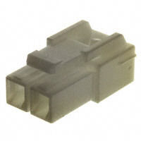
CN6 2-Pin Connector, JST, Digikey Part Number: 455-1165-ND
CN3, CN5, and CN6 Connector Pins, JST, Digikey Part Number: 455-2148-1-ND
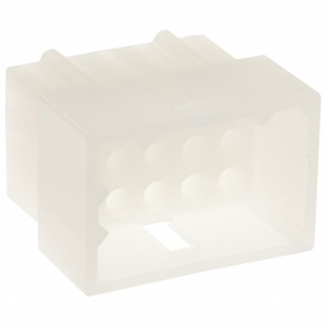
TK-981 KCT-19 15 Pin Molex Connector Plug, Receptacle, Male Pins, and Female Sockets
If you are going to be using or building your own KCT-19 and are in need of the 15 pin Molex connector Plugs, Receptacles, Pins, and Sockets then below you can find part numbers and datasheets. The Molex parts are available from Digikey.
Molex Inc. KCT-19 15 Pin Connector Datasheet
Molex Inc. KCT-19 0.062" Male Pin Datasheet
Molex Inc. KCT-19 0.062" Female Socket Datasheet
Molex 15 Pin Plug is Digikey Part Number: WM1228-ND
Molex 15 Pin Plug Male Pins are Digikey Part Number: WM3680CT-ND
Molex 15 Pin Receptacle is Digikey Part Number: WM1238-ND
Molex 15 Pin Receptacle Female Sockets are Digikey Part Number: WM9118TR-ND
TK-981: A Different Look
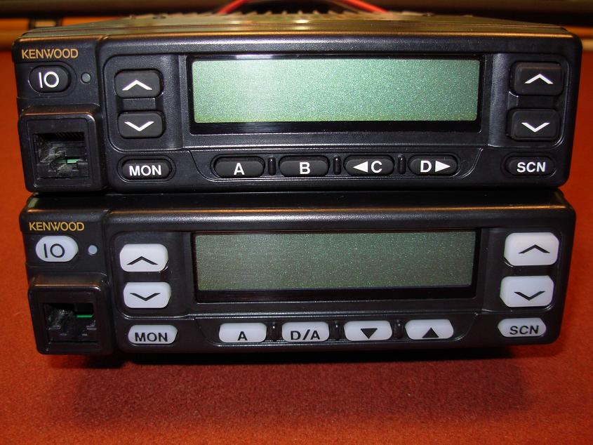
If you want a different looking TK-981 front panel or are thrifty and looking to save a little when replacing your worn out Silicone Button Keypad there is an alternative to the original black keypad: a keypad for the TK-760HG/860HG. This keypad is white/clear and will add a totally different look to the TK-981, and as an added bonus it is also quite a bit cheaper than the original Silicone Button Keypad on the TK-981. You will notice that on the 760HG/860HG the original "B" button is replaced with a "D/A". The Silicone button keypad can be purchased from East Coast Transistor or Pacific Coast
Parts; the part number is K29-5343-12.
Pictured below is the original TK-981 (top) Silicone Button Keypad, shown below it is the keypad from a TK-760HG/TK-860HG.
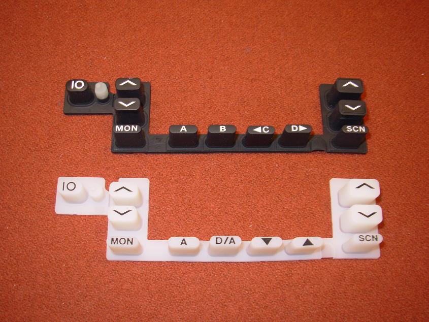
The Silicone button keypad from a TK-760HG/860HG will add a totally different look to the 981!
TK-981 Test Frequency Edit
If you want to change the test frequencies on the 981/481 there are 2 ways to edit them. One way of getting amateur frequencies into the test frequency menu is by editing KPG-49D.exe, as the test frequencies are very easy to find with a Hex editor- I am not going to go into this any further for obvious reasons. The other way of editing the test frequencies is by editing the saved .DAT file that KPG-49D or KPG-35D save when you create a new program file.
There are 10 pre-programmed commercial test frequencies that are in each saved .DAT file. The following test frequencies are saved:
- 935.0250MHz
- 935.0500MHz
- 938.0000MHz
- 938.0250MHz
- 939.9875MHz
- 940.4000MHz
- 940.9000MHz
- 936.2500MHz
- 939.3000MHz
- 936.7500MHz
The above test frequencies are the receive/talkaround test frequencies, the transmit frequencies are not shown but are 39MHz lower from the receive- this is the 900MHz commercial band repeater input range. It is very easy to modify these frequencies in the saved .DAT file when you look at how they are saved. Using the Hex editor of your choice, I use HexEdit open a TK-981 or TK-481 saved .DAT file and look at line 170, that is the starting point in the file where the test frequencies are. On line 170 pictured below we see our test frequencies:
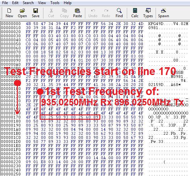
Our first test frequency is seen on line 170: 00 25 50 93 is the Receive and TA frequency and then we see 00 25 60 89 which is the transmit frequency. This corresponds to 935.0250MHz and 896.0250MHz our channel 1 test frequency.
Our second test frequency is seen on line 170 and continues on to line 180 which is 00 50 50 93 and 00 50 60 89 or our channel 2 test frequency of 935.0500MHz and 896.0500MHz.
Our third test frequency is seen on line 180 and continues on to line 190 which is 00 00 80 93 and 00 00 90 89 which is our channel 3 test frequency of 938.0000MHz and 899.0000MHz.
Our fourth test frequency is seen on line 190 which is 00 25 80 93 and 00 25 90 89 which is 938.0250MHz and 899.0250MHz our channel 4 test frequency.
Now that we see how the test frequencies are saved we can edit them with our Hex editor and save the file. Open the .DAT file with your Hex editor and edit the test frequencies with whatever frequencies you would like by changing the Hex.
Here are some examples of what amateur frequencies would be:
927.0125MHz would be 50 12 70 92 and the transmit frequency of 902.0125MHz would be 50 12 20 90
927.9875MHz would be 50 87 79 92 and the transmit frequency of 902.9875 would be 50 87 29 90
927.5000MHz would be 00 00 75 92 and the transmit frequency of 902.5000MHz would be 00 00 25 90
If you are going to change the filters and adjust the VCO to receive at 918.0000MHz then 00 00 80 91 would be the receive and the transmit would be 12MHz down or 906.0000MHz which is 00 00 60 90
TK-981 Copy and Paste Feature in KPG-49D Versions 4.xx
This feature is very handy for changing and modifing any saved .dat file in KPG-49D version 4.xx (Windows based versions) for your Version 1 or 2 TK-981. This feature allows you to move around a frequency to another System/Group without having to re-run KW900EZP.exe each time. See steps/images below for further details:
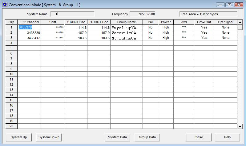
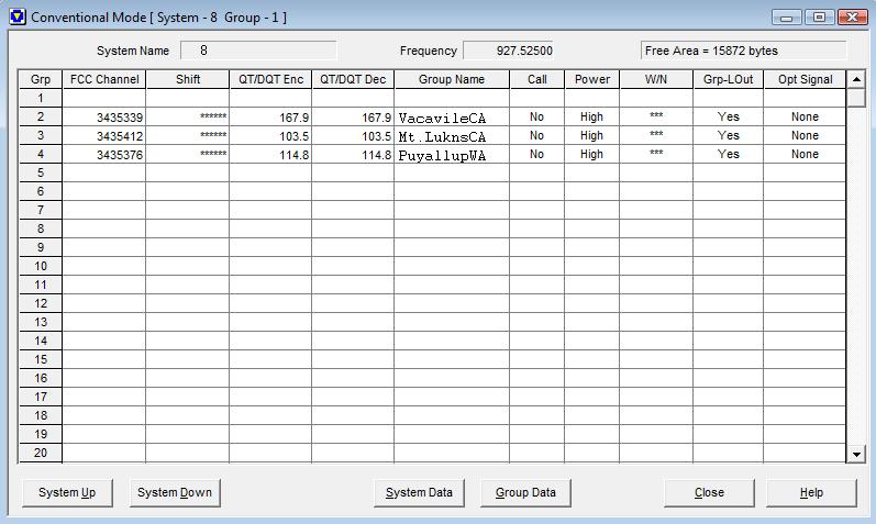
- In this screen shot selected is the "PuyallupWA" repeater in System 8 Group 1 and we want to move it a couple Groups down to System 8 Group 4- as an example. So we need to click on the Group 1 "PuyallupWA" Repeater FCC Channel number until it turns blue. Once blue press and hold the "CTRL" key and "C" to copy the contents of the FCC Channel box in Group 1.
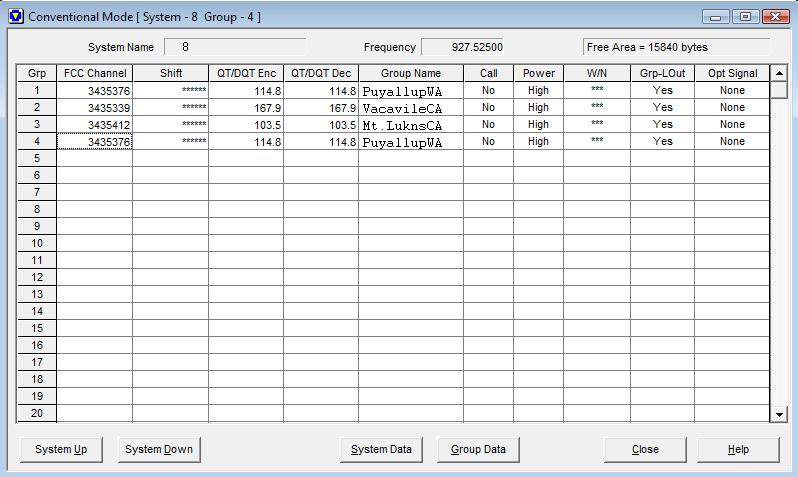
- Once copied we can move the "PuyallupWA" repeater contents where ever we would like, into any System/Group. To paste the contents of the previous step into a different Group we can press and hold the "CTRL" key and "V" and the contents will paste into where ever we have selected- make sure you select where you want to paste the previous contents to by clicking on a used or empty Group under the "FCC Channel" box. Pictured below we have pasted them in System 8 Group 4- we can move this repeater to System 5 Group 6, System 2 Group 15 or anywhere in the file that we want- I chose to use System 8 Group 4 as an example of how copy and paste works.
- We can now delete the "PuyallupWA" repeater found in System 8 Group 1 and insert any repeater we want in its place by entering a new FCC channel number or using copy and paste to move another repeater from a different System/Group. Using the copy and paste method means you do not need to re-run KW900EZP.exe!
TK-981 Version 1/2 Programming copy from TK-481 Version 2
If you happen to own a Version 2 TK-481 and have it programmed the way you want it and you happen to own a Version 1/2 TK-981 you can painlessly program that radio using the file you have in your Version 2 TK-481! To do this you must be using KPG-49D Versions 4.xx (Windows based versions). This also works the other direction, if you own a TK-981 Version 1/2 and want to program a TK-481 Version 2 handheld- the key is to make sure that you have the "Fleetsync Enhanced Function" checkbox UNCHECKED when doing this as mentioned in step 3.
The how to is as follows:
- Run KPG-49D and open your TK-481 Version 2 .DAT programming file.
- Go to the "Model" menu at the top of the program and select "Model Information".
- You should have "Fleetsync Enhanced Function" unchecked and the model radio shown should be "TK-481[Portable]" OR "TK-481[Portable](Key Pad Model)" if you have a DTMF TK-481.
- Go to "TK-481[Portable]" OR "TK-481[Portable](Key Pad Model)" and select "TK-981[Mobile]", click "Ok".
- You will get a message stating "Key and COM data will be cleared", click "Ok"
- You will have to configure the TK-981 front keypad assignment i.e. select which front panel buttons you want to do what and it would be a good idea to go through and select and double check all the option menu's.
- Save the file as a different name and enjoy the painless transfer of all your TK-481 Version 2 memories!
TK-981 Power Plugs
The power connectors on the TK-981 are made by JST and available from Digi-Key.
JST VL Series Power Connector Datasheet
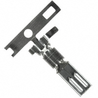
The plug that is located on the radio pigtail is Part Number 455-2355-ND. The pin that fits this connector on the TK-981 radio pigtail is Digi-Key part number 455-2379-1-ND.
The TK-981 power cord connector is Digi-Key part number 455-2374-ND and the pin that fits the power cord plug is Digi-Key part number: 455-2376-1-ND