Kenwood TK-981 for Repeater Use
The TK-981 has not previously been covered as a possible repeater candidate due to it being such a great radio for general ham use. Now that the Kenwood NX-901 has been around for several years and due to the large quantity of TK-981's showing up on the used market the radio can now be used as a repeater.
The TK-981 as a Repeater Receiver
The VCO of the TK-981 is adjustable just the same as the TK-941 radio, however, the VCO's are not the same between the 2 radios and there is one issue that exists on the TK-981 VCO that does not exist as much on the TK-941. It should be noted after the previous statement that some TK-981's will lock at 902.xxxxMHz and some will not; the VCO voltage at TP1 must be 1.0Vdc or more at 902.xxxxMHz! Before any hardware modifications are performed program your TK-981 for your 902.xxxxMHz receive frequency. After programming the radio for your 902.xxxxMHz receive frequency, adjust the VCO voltage, if you have less than 1.0Vdc there are three things you can do; 1. Disassemble the VCO and swap out 3 SMD capacitors 2. Try another TK-981 to see if that will work 3. Use the VCO from a TK-980 (800MHz) radio and swap it into the TK-981 and readjust. If you need to remove and modify the VCO on the TK-981 please see the Files section of this website for the modification that will need to be done; PDF courtesy of Tom Appel, K5TRA.
It should also be noted that the RX filters will need to be changed out- this holds true for ANY 900MHz radio (Kenwood, Motorola, GE, or EF Johnson) if you want to receive at 902.xxxxMHz. Removing the filters is best done using hot air. Hot air has long been a standard for work with SMD applications and it works really well for removal of the filters in the TK-981 and TK-941.
To Program a TK-981 for a 902.xxxxMHz Receive frequency:
- Run KPG-49D
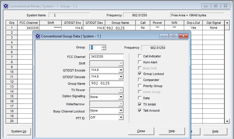
- Program in 1 System with the FCC ID of your repeater RX frequency pair (FCC ID 1 is 935.0125MHz is what I chose)
- Under The "Group Edit" box for that System ensure you have the "TX Inhibit" and "Talk Around" boxes checked, as well as give the Group a name such as "902.0125".
- Under the "Optional Features" section then "Optional Features 1" of KPG-49D ensure "Off Hook Decode" is selected, "Signaling" is selected as "AND". Under the "Optional Features 2" tab we can set up our Receive Logic. Under the "Logic Signal" section "Squelch Logic Type" select if you are going to use "Active Low" or "Active High", and then under "Squelch Logic Signal" select "TOR" (Tone Receive), "COR" is carrier receive and ignores the RX Tone programmed.
- Save the file and using the Hex editor of your choice open your saved .dat file
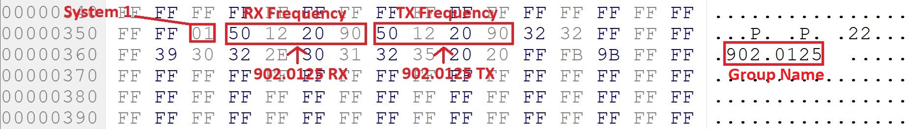
- On line 0350h you can see your first and only System programmed, hex edit your frequency as needed . The RX and TX frequencies are in plain sight but jumbled up the same as how the test frequencies are shown. I have the RX and TX frequencies programmed as 902.0125 in the picture shown below. If hex editing isn't your thing you can use KW900EZP with EZ-Edit and just type in the frequency you need.
- Using a VOM adjust the VCO for the highest voltage obtainable as measured at TP1. This voltage will vary depending on the VCO but needs to be 1.0Vdc or more, some radios will work just fine, more times than not, they will not. If your radio VCO voltage is less than 1.0Vdc then you will have three options to choose from:
- Disassemble the VCO and swap out 3 SMD capacitors
- Try another TK-981 to see if that will work
- Use the VCO from a TK-980 (800MHz) radio and swap it into the TK-981 and readjust
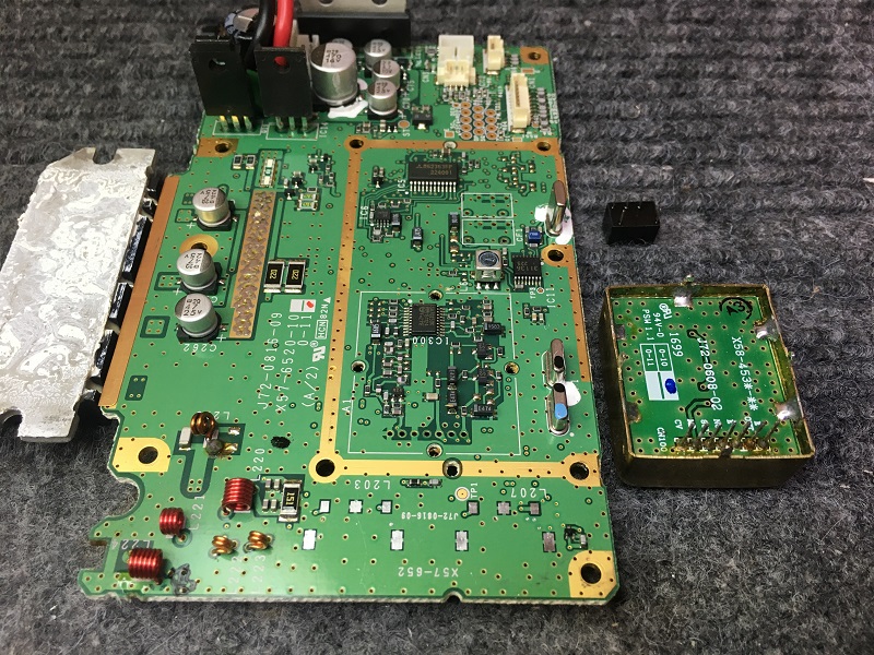
- If you are not lucky enough with the VCO on your TK-981 you can remove the VCO and disassemble it and change out the 3 SMD capacitors. With the radio disassembled you can also change out the original 938MHz receive filters for those that are centered at 915MHz. In the picture shown below the VCO is removed by de-soldering the 4 mounting tabs and then de-soldering pins 1 through 7 from the main PCB of the TK-981. After Removal of the VCO you will need to remove solder from 3 sides of the VCO that connect from the brass housing to the VCO PCB- a total of 5 solder connections; after removing solder open the VCO up. After VCO disassembly follow the "How-To" in the files section of this website for modifying the VCO.
- After the VCO is modified you can reinstall it and add the receive filters, shown below are Toko 2-pole SMD filters.
- A BNC connector can be used directly mounted to the radio chassis, if so desired. For the how-to on adding a BNC chassis mount connector to the radio chassis see the Repeater section of this website under the TK-941 exciter section.

The TK-981 as a Repeater Exciter
The TK-981 setup as a repeater exciter is very straightforward, with a little variation depending on what power out of the radio you need. To program the radio for a 927.xxxxMHz Repeater Output frequency you can program it using KPG-49D and KW900EZP.exe or you can Hex edit the frequency.
To Program a TK-981 for a 927.xxxxMHz transmit frequency:
- Run KPG-49D
- Program the desired 927.xxxxMHz frequency by selecting the corresponding FCC ID found in KwID.exe or the FCC ID to frequency Chart- so for example 927.0125MHz would be FCC ID #1.
- Set the desired Time Out Timer time to 10 minutes and set all other settings as desired.
- Be sure to set "TlkArnd" in the program to "YES"- this is because of how KW900EZP.exe works, anything with Talk Around enabled will be a 927.xxxxMHz frequency.
- Save the file and run KW900EZP.exe and then reopen your saved file in KPG-49D, ensure that the desired transmit frequency is showing, adjust all settings in Test Mode such as max deviation, tone deviation, power out, etc...
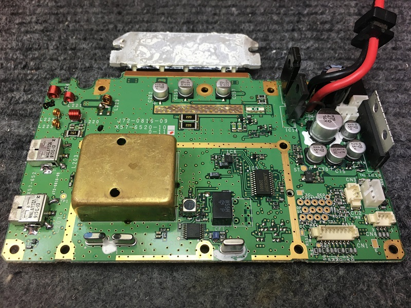
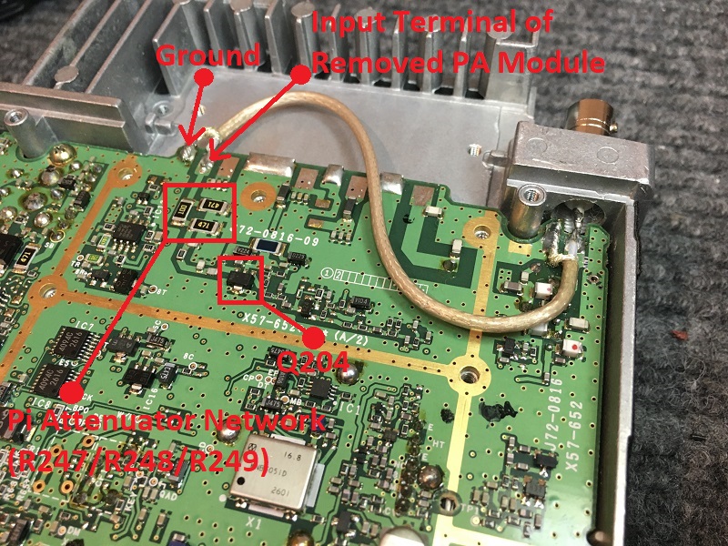
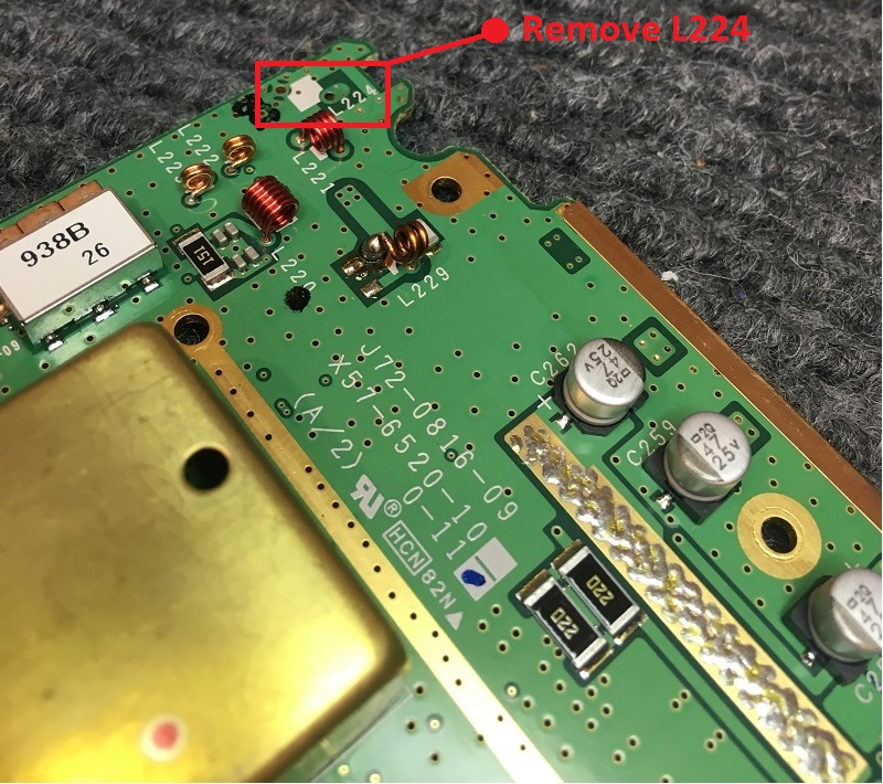
The TK-981 can be configured to run as a very low power (350mW Output) exciter or as 6-10 Watt exciter depending on what amplifier is being used. If you are going to run the exciter as a 6-10 Watt radio you will need to either add a small cooling fan or install the radio in a long heatsink chassis- see the "TK-981H" or "TK-981HH" sections of this website for the how-to. To get 350mW output from the TK-981 you must remove the Mitsubishi PA module and solder a small length of RG-316 coax to the input pin of where the Mitsubishi M67760HC PA module was previously installed. We will be using the FET Q204 (2SK2596) pre-drive module for our output power of the radio. Pictured below is a TK-981 set up for 350mW output. If you need more power out than 350mW you can remove the Pi attenuator network (1/2 Watt; R247/R248/R249) and install a Zero Ohm jumper in place of R247 after it is removed. The RG-316 coax runs from pin 1 of where the original PA module would have been to the output of the radio terminal and output via a chassis mounted BNC connector. After routing the coax to the output terminal of the radio you must remove the coil L224 as shown in the picture below. After all modifications are made you will need to file a small round groove to feed the coax through the RF shield that covers the main PCB, this shield MUST be re-installed. For the how-to on adding a BNC chassis mount connector to the radio chassis see the Repeater section of this website under the TK-941 exciter section.
Using a KCT-19 interface cable all signals needed for interfacing with your repeater controller of choice are available. The pinouts of the KCT-19 15-pin Molex connector on the TK-981 are as follows:
Pin 2 "ME"- TX Input; Microphone Ground
Pin 4 "DEO"- RX Output; Detector Audio Out (unfiltered, pre-emphasized audio out)
Pin 5 "MI"- TX Input; External Microphone into radio
Pin 6 "E"- Ground
Pin 7 "SB"- Output; Switched +13.8Vdc out of radio (1 Amp maximum)
Pin 8 "PTT"- TX Input; External PTT to Radio- Program "COM2 (Internal Port)" as "AUX Hook/PTT"
Pin 11 "SQ"- RX Output; COR or TOR- Program "Squelch Logic Signal" as "TOR" and "Active High" or "Active Low"; TOR is "Tone Operated Relay" and COR is "Carrier Operated Relay"