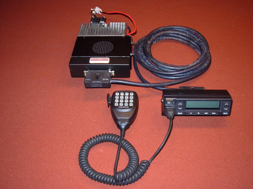
The 45 Watt TK-981HH
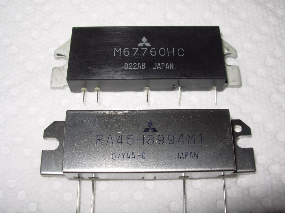
Like the TK-981H 30 watt radio this also was never produced by Kenwood. The TK-981HH is a 45 Watt radio and is the coolest thing since sliced bread. The modification is not for the beginner, nor is it cheap, this is an advanced project which utilizes a chassis from a dead TK-880H (a TK-780H, TK-760HG, TK-860HG, TK-762HG, and TK-862HG will also work) for the longer heatsink, a 45 Watt Mitsubishi RA45H8994M1 PA module. This PA module is a MOSFET and can handle some serious use and abuse, just looking at the metal housing you can tell from a design standpoint it was intended to get warm!
The radio internals are what must be modified and unfortunately you cannot use the original board (Pre-serial number 60600001) to do this modification.
To construct a 45 Watt TK-981HH there are essentially two routes you can take:
- ROUTE 1: If you have a PRE-60600001 serial number TK-981 you will need to rob parts from it and also need to buy the newer 60600001 serial number board from East Coast Transistor or Pacific Coast Parts, this is Kenwood part number X57-6520-11A/2. You will need to salvage parts from your donor radio as well as order the following parts to construct your 45Watt TK-981:
- Speaker
- Front Panel
- Top and Bottom Panels
- All Top/Bottom Panel Screws
- Retaining Clips-located on the audio amp, 8Vdc Volatge regulator
- Coax Pigtail w/Screws
- Power Cord
- RF Bottom Panel (PA Cover/Shield)
- Front LCD
- Silicone Button Assembly
- Front Ribbon Connector
- You will need to remove Item 10 as pictured in the TK-981 Suppliment Service manual (See "Downloads" Section of website), this is called the "Ground Terminal" by Kenwood and Part Number E23-1136-04, which is NOT sold by East Coast Transistor or Pacific Coast Parts
- You will also need to REMOVE D208, as shown in the TK-981 Supplement II Service Manual (See "Downloads" Section of website) the PIN Diode, this is Kenwood part number MA4PH633
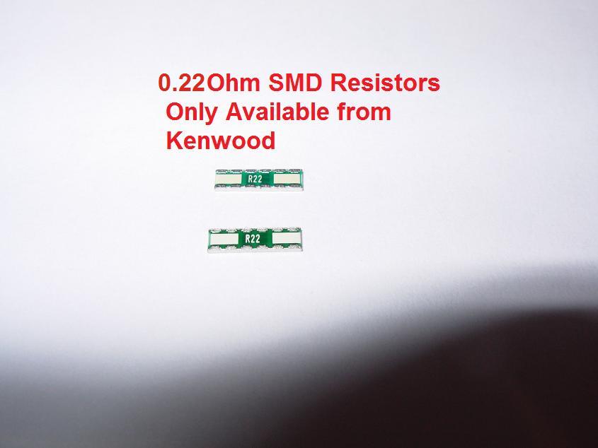
- You will need to order Two 0.22 Ohm SMD Resistors Kenwood Part Number R92-2682-05, this can be purchased from East Coast Transistor or Pacific Coast Parts
- You will need to buy the new main board, this is the serial number 60600001 and up board and is Kenwood Part Number X57-6520-11A/2, this can be purchased from East Coast Transistor or Pacific Coast Parts
- You will need a Service monitor or signal generator if you decide to go Route 1, as you will need to tune Coil L6, as found on page 8, Grid Location 11H, of the TK-981 Supplement II Service Manual (See "Downloads" Section of website), for maximum AF.
- You will also need to order/acquire items 1 through 7 EXCLUDING item 3- if you removed it from your donor radio.
- ROUTE 2: If you have a TK-981 Version 2 Serial Number 60600001 or above you will need to buy items 1 thru 7 listed below.
Before getting started please reference the PDF Datasheets for the Mitsubishi Power Modules listed above.
Mitsubishi RA20H8994M Higher Power PA Module (4 pin/Starting Serial 60600001)
Mitsubishi RA45H8994M1 45Watt High Power PA Module
You will need the following Tools:
- 40-50 Watt Pencil Tip Soldering Iron with Solder Wick
- Hot Air Rework station is Optional- Makes the job easier!
- Bird/Telewave Wattmeter- This is NOT optional- you will need one!
- 900MHz 50W Slug if using a Bird Wattmeter
- 50 Watt Dummy Load-This is NOT optional- you will need one!
- Micro Phillips Head Screwdriver
- Normal Phillips Head Screwdriver
- X-ACTO Knife
- Liquid Solder Flux
- Heat Sink Thermal Compound (Zinc Oxide)- This is NOT optional
You will need the following Parts:
- One Mitsubishi RA45H8994M1 PA module- can be purchased from RF Parts Company, you can find the link to their website via the "Links" section of this website.
- Two 0.22 Ohm SMD Resistors Kenwood Part Number R92-2682-05, this can be purchased from East Coast Transistor or Pacific Coast Parts.
- One PIN Diode Kenwood Part Number MA4PH633, this can be removed from your donor radio or purchased from East Coast Transistor or Pacific Coast Parts.
- One 1000pF SMD Ceramic Capacitor Size 0805
- One 1/8watt 20K Ohm Axial Lead Resistor
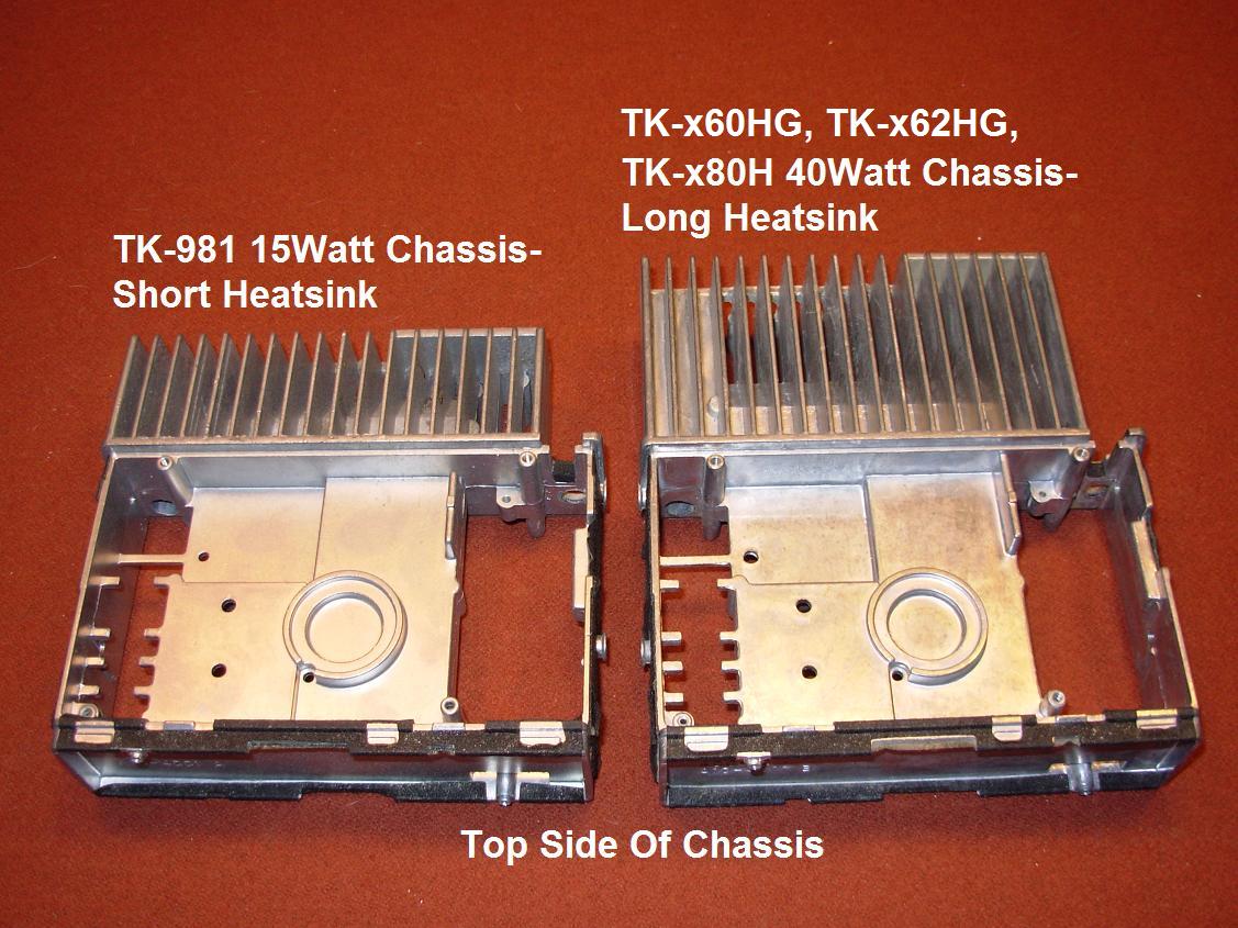
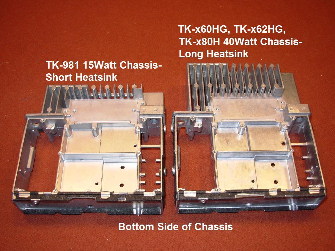
- A dead TK-780H, TK-880H, TK-760HG, TK-860HG, TK-762HG, or TK-862HG to salvage the long heatsink chassis from it, as a short heatsink TK-981 does not have enough heat disapation for the larger PA module- This larger heatsink chassis is NOT optional and is required!
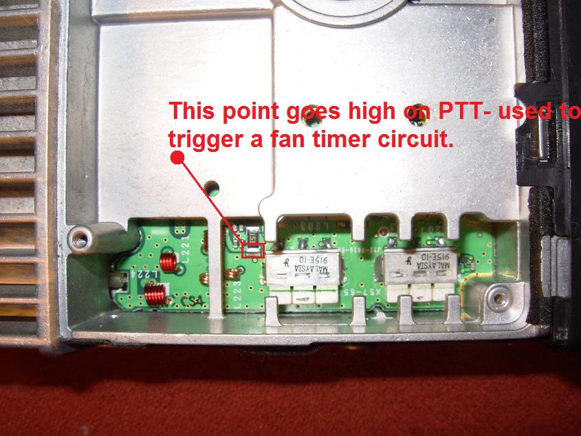
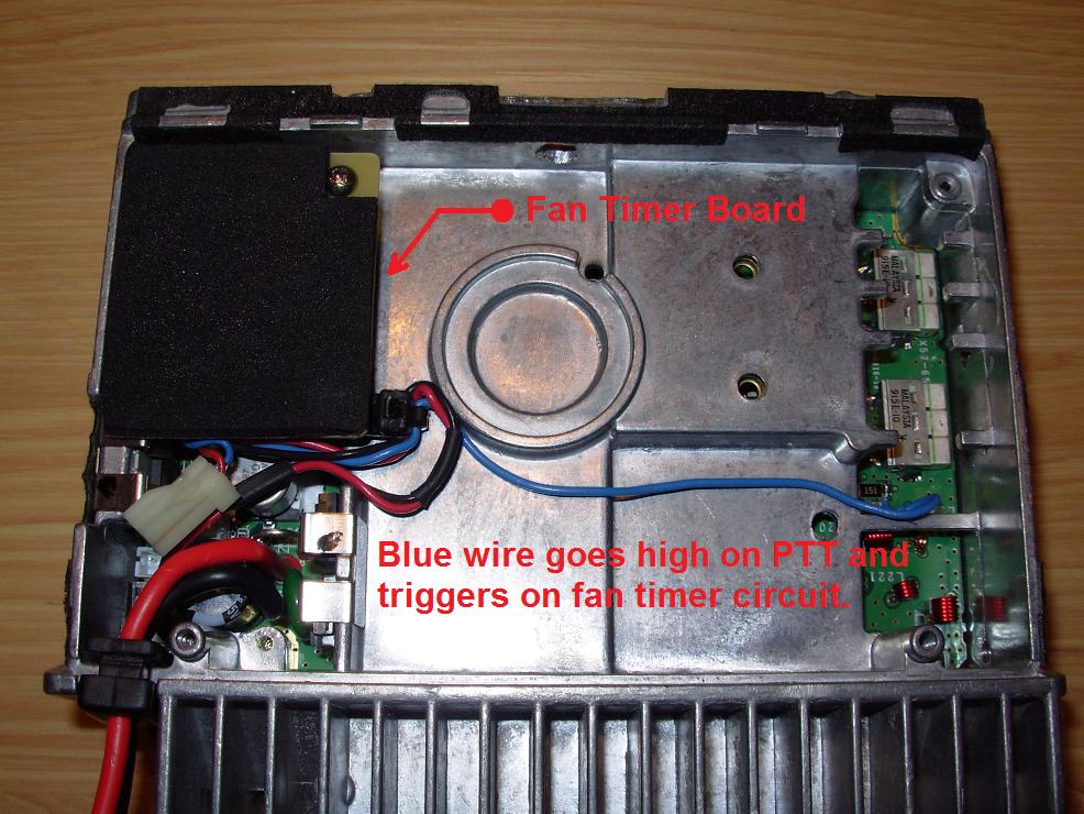
- 40mm cooling fan for cooling the radio during long transmissions and a timer circuit or thermal switch to control when the fan powers on or off. I use a 2 minute timer circuit which uses a simple 555 timer triggered on by the PTT.
BEFORE WE START:
Make sure that you understand that this modification is NOT for the beginner or even moderate beginner, it requires good knowledge of proper soldering techniques, soldering of Surface Mount Devices (SMD's), and the proper test equipment. SMD's are delicate and not terribly easy to work with. Know YOUR limitations and don't try to do this modification if it is beyond your current skill level. YOU HAVE BEEN WARNED! You should also be aware that modifying this radio will nullify the radios type-acceptance for use in commercial service.
- The first step is acquiring a TK-780H, TK-880H, TK-760HG, TK-860HG, TK-762HG, or TK-862HG long heatsink chassis. These long heatsink chassis are not available from Kenwood, so you will have to find one via the used market. You are looking for a dead, non-working TK-780H, TK-880H, TK-760HG, TK-860HG, TK-762HG, or TK-862HG- as long as the chassis is in one piece thats all you need- I have had great luck on eBay contacting sellers and asking if they happen to have one laying around- usually $40 to $50 will get you what you need including shipping. Pictured below is the main reason we are going to go with the longer heatsink, the surface area of the "H" chassis is much more allowing better cooling of the PA module.
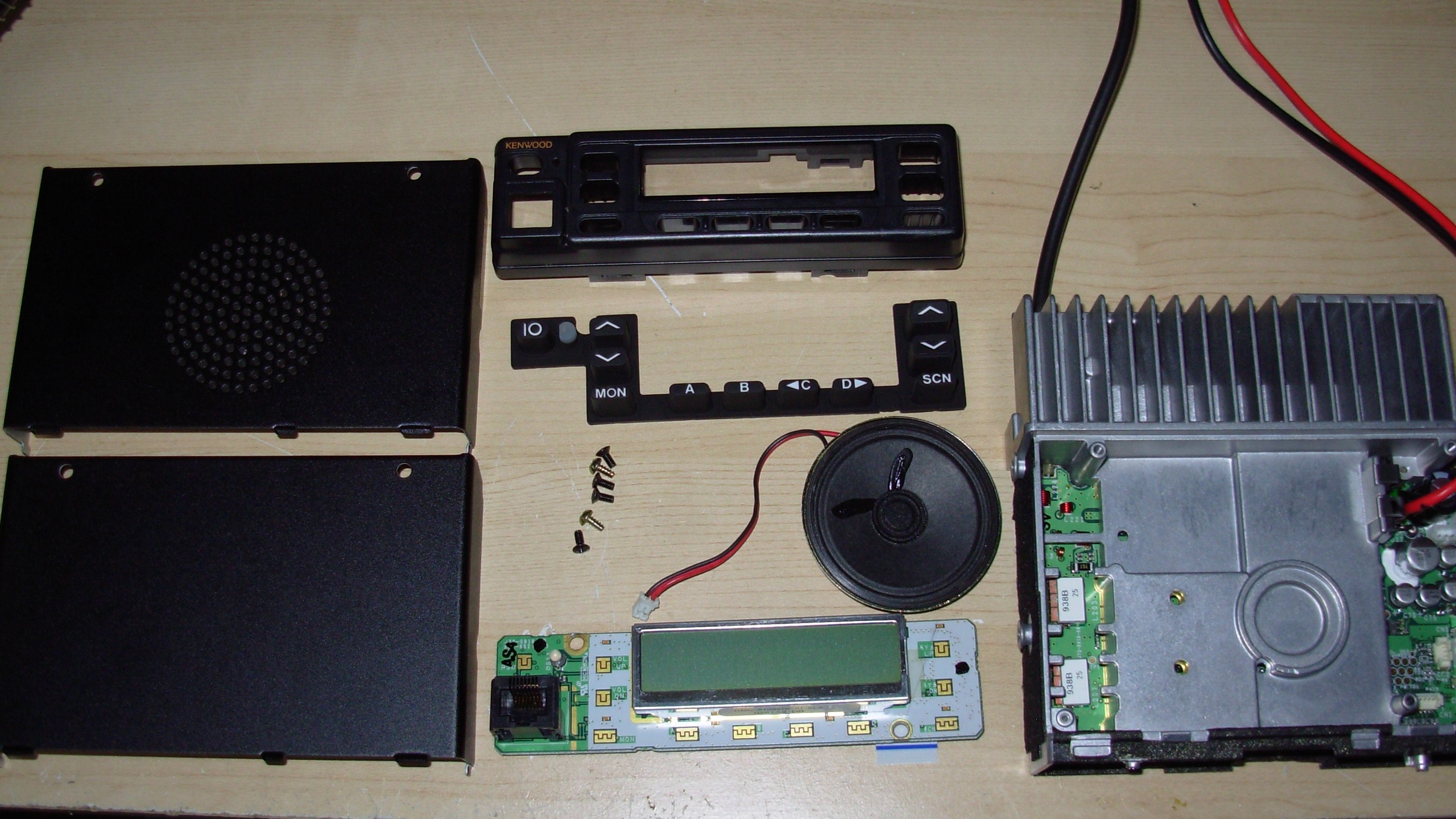
- If you happen to have a TK-981 serial number 60600001 or higher ensure that your radio is working properly and functioning correctly, there is no point in modifying a radio that is damaged. Since all this was covered in the TK-981H step-by-step how to I am going to skip all the pictures involved with disassembling the radio. As an added note if disassembly of your TK-981 is terribly difficult for you, then stop, this project is not for you! We need to remove the top and bottom covers of the radio, the speaker, the front panel and display. Removal of the display will require you to unplug the ribbon cable in the front bottom of the radio- be very carefull in doing this! We also want to remove the clip that holds the audio PA securely to the chassis, and the clip that the 7808 Voltage regulator and the APC drive transistor to the 981 chassis. Flip the radio over and remove the large RF shield that covers the PA module. We also want to remove the 2 screws holding the coax pigtail in place and de-solder the the coax pigtail and remove it, be carefull in doing this, as too much heat can remove the trace from the main board. You will also want to remove the existing PA module from the main RF board. I have found that a combination of a solder bulb sucker and solder wick are best in removing the large globs of solder from the PA pins. It would be a good idea to save the old PA for a spare or to sell it to try an recoup some of the money spent on the higher power PA. Also at this step you will need to remove all the securing screws that exist on the bottom side of the board to facilitate removal of the entire assembly.
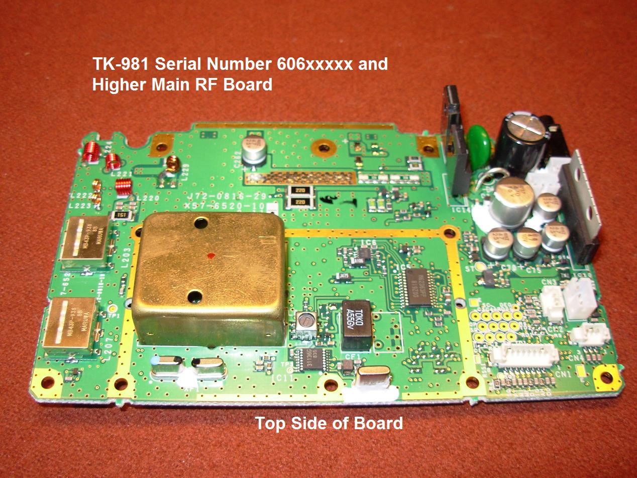
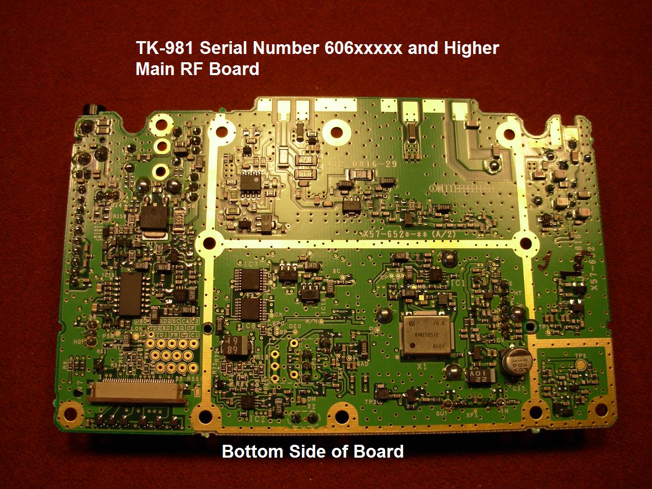
- At this point you have either disassembled your serial number 60600001 and up TK-981 complete radio and have the main RF board ready to be modified or are ready to modify the newly purchased RF Board from East Coast Transistor or Pacific Coast Parts using your donor radio parts.
- The Mitsubishi RA45H8994M1 PA module requires a 3.4Vdc bias on pin 1- the RF input pin. To inject 3.4Vdc on pin 1 of the RF module we must block this DC from the predrive module upstream. To block DC voltage from the predrive module we are going to install a DC blocking 1000pF SMD ceramic capacitor. We must make a cut on the trace leading to pin 1 on the PA module. This cut is to allow us to install a 1000pF SMD capacitor. Cut the trace EXACTLY as shown, i.e. in the same location and as close to as pictured as possible!
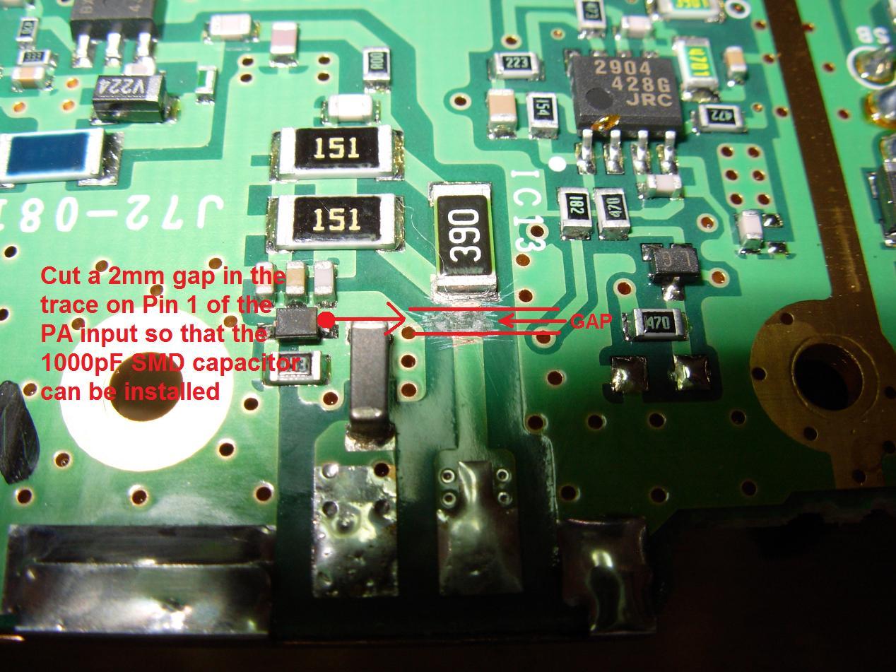
- Now that we have made the cut in the trace leading up to pin 1 of the PA module we will need to install it, to do so scrape some of the green coating off the trace and install the 1000pF SMD capacitor.

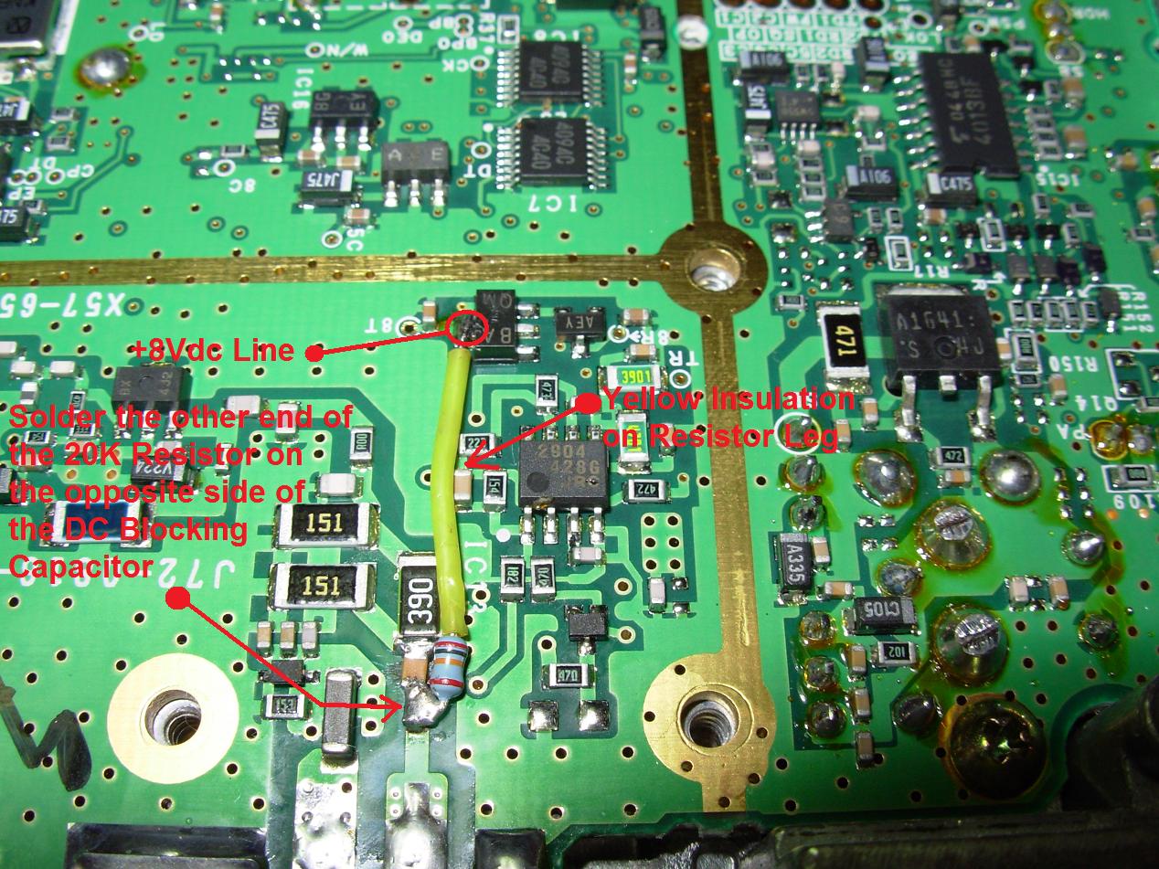
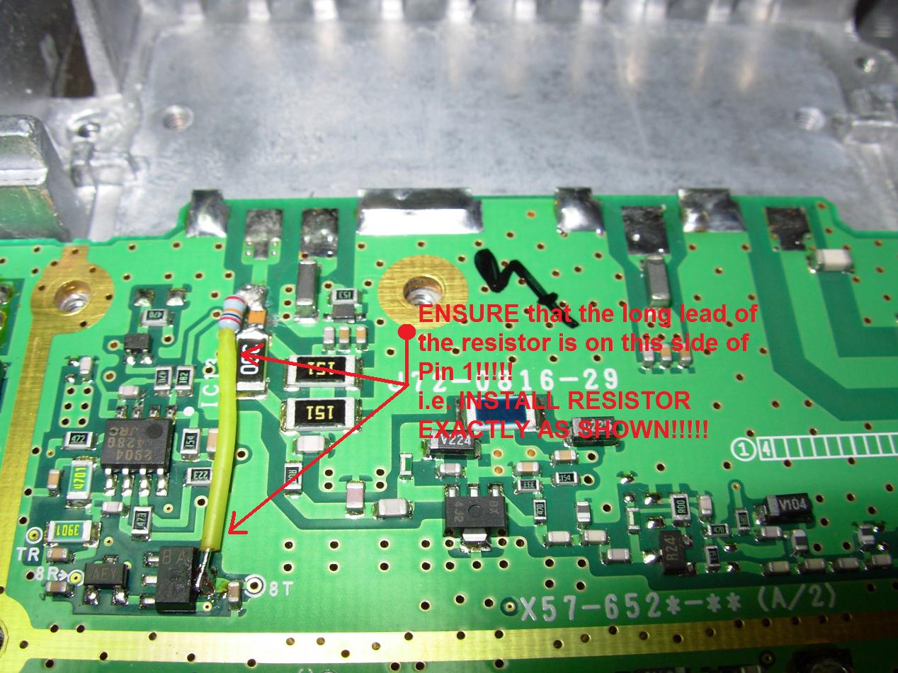
- We are now able to install our supply of 3.4Vdc to pin 1 of the PA module via an 1/8th Watt 20K Ohm Resistor. The resistor will drop a regulated +8Vdc down to our needed 3.4Vdc pin 1 input. It is VERY important to mount the resistor EXACTLY as shown in the pictures below with the long lead on the opposite side of Pin 1- YOU MUST INSTALL IT THIS WAY!
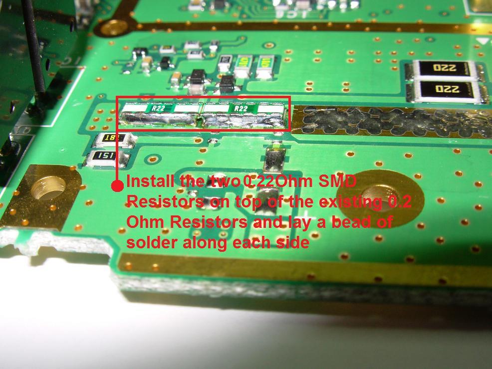
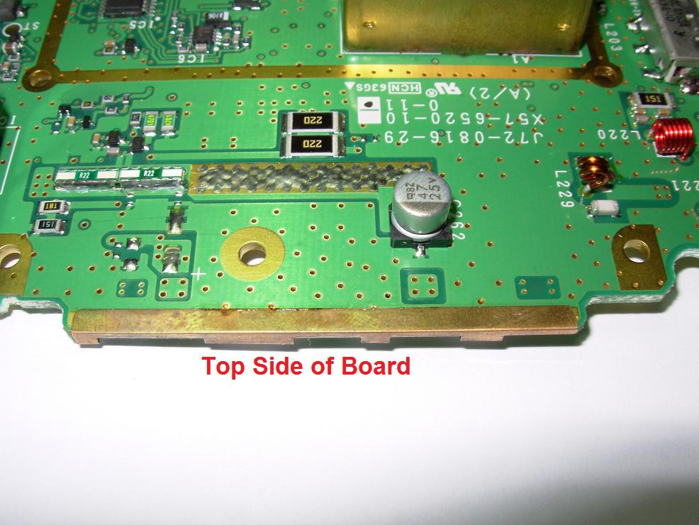
- Now we will install the two 0.22 Ohm SMD sensing resistors on the other side of the board from where we have been working for the APC circuit. The Resistors are a little unique in that the terminals run along the length of the resistor and not at either end which is why it is important to get this item from either Pacific Coast Parts or East Coast Transistor.
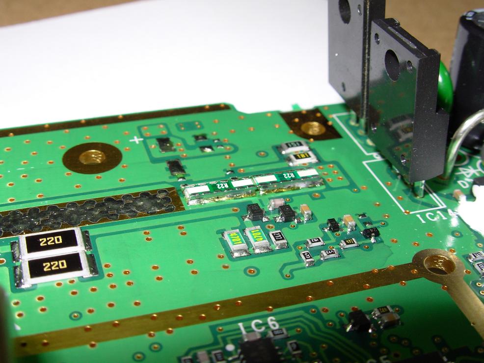
- We can now install each 0.22 Ohm Resistors in the APC circuit on the top side of the TK-981 main board. I simply stacked one resistor on top of the other one and ran my soldering iron down each side. For clarification here; you are stacking one resistor on each of the two resistors that are already on the board- see pictures below.
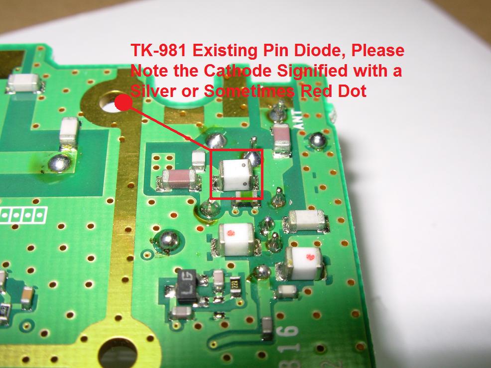
- To handle the increased RF output and therefore increased heat we must double up our transceivers PIN Diode. This Diode can be seen near the RF output of the radio and note the RED or SILVER dot to indicate the Cathode of the Diode.
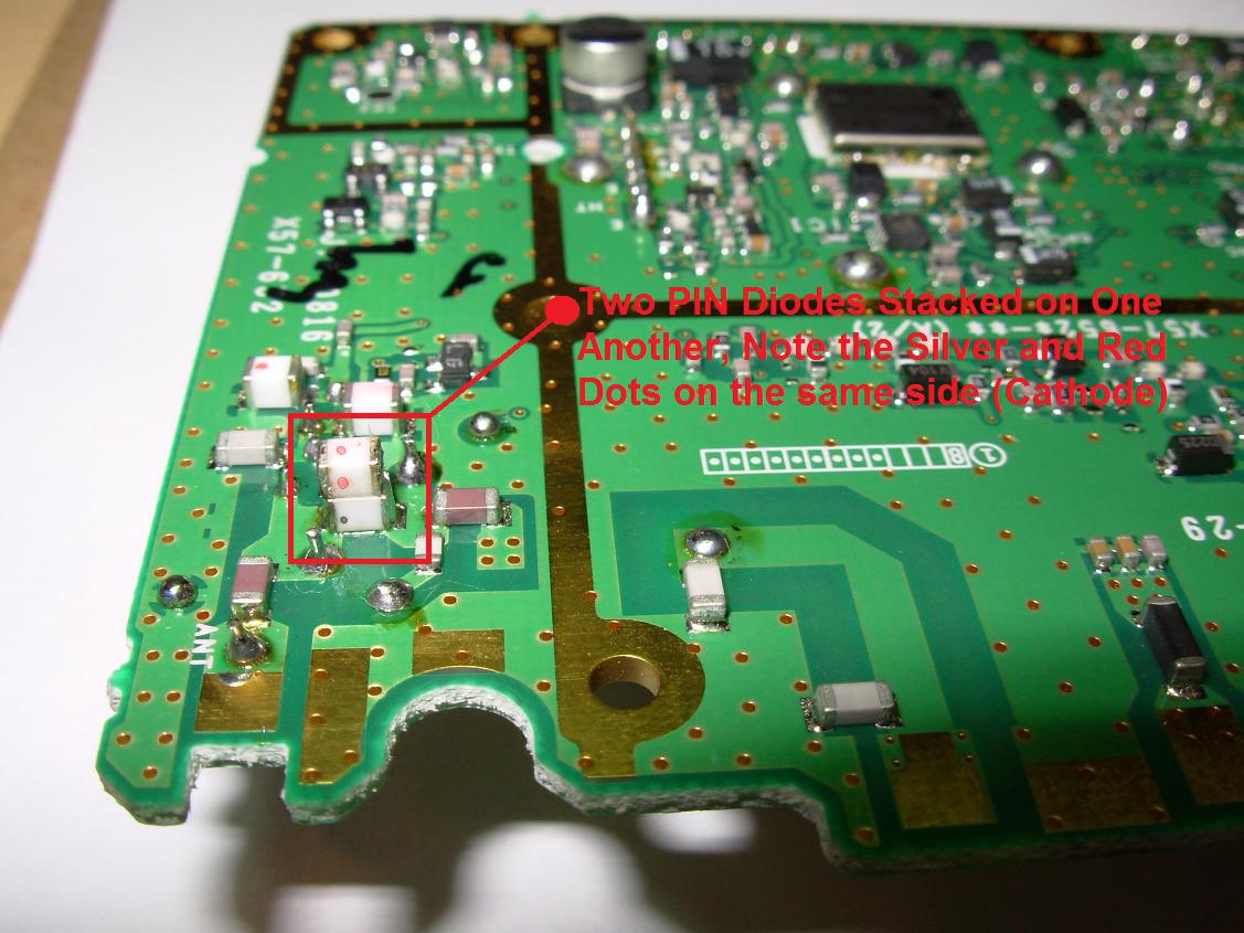
- We can now stack our additional PIN diode on the existing PIN diode be very carefull to observe the red or silver dot indicating the Cathode of the diodes.
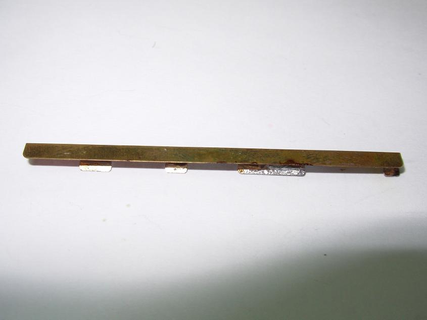
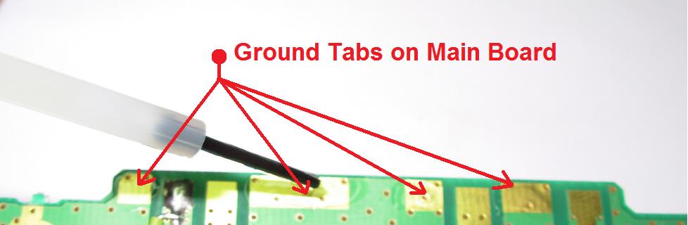
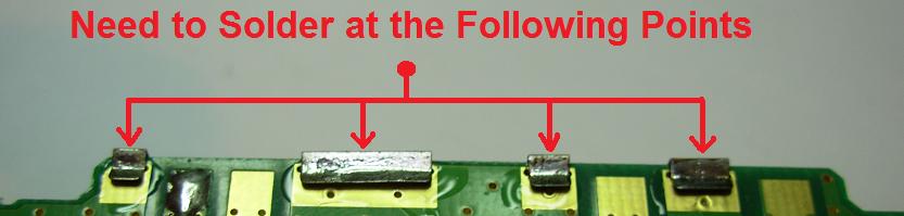
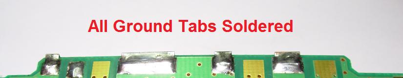
- If you are modifying your existing TK-981 Serial number 60600001 or higher then you can skip this step and move on to Step 12. If you bought the new main RF board and you are reusing parts from your PRE-60600001 TK-981 then you will need to add the below pictured ground tab on the back of the main board of the radio. This ground tab joins the top and bottom of the main board ground planes. You will need to remove the existing ground tab off of your donor TK-981 Version 1 or 2 radio and solder it in place on the new 60600001 or higher serial main board. See the following pictures for further information.
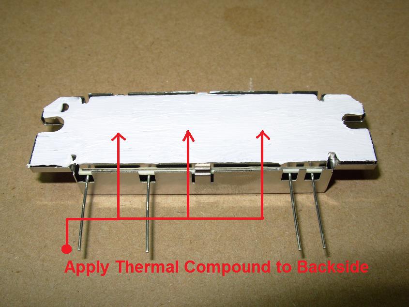
- At this point we can now reassemble the radio in the new longer heatsink chassis- you can install the board and reattach the coax pigtail, power cable, front LCD with ribbon cable and buttons also the front plastic display.We are now able to install the new PA module in its new home. Looking at the below picture we see a big difference in the Pre-60600001 Serial number PA module and our new 45Watt PA module.
- We need to apply thermal compound (heat sink compound) to the backside of the PA before installing. This will better conduct heat away from the PA to the external heatsink.
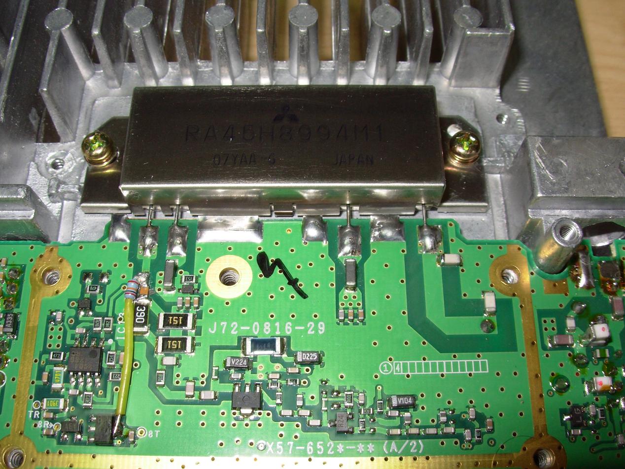
- Place the new 45 Watt PA module in the new longer heatsink chassis secure the PA with the secureing screws to the chassis, align and trim pins 1 through 4 to the main board, and and solder the pins in place. Remove all excess solder flux using solder flux remover or Isopropyl Alcohol of at least 90%.
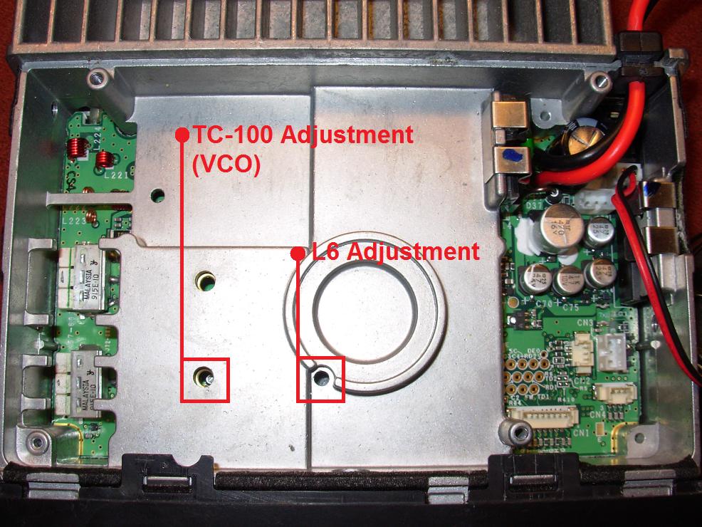
- If you are modifying your serial number 60600001 and up radio, Route 2 as mentioned above, then you can skip this step and move on to step 16. If you are going the way of Route 1 as mentioned above and using the parts from your donor radio and the new post serial number 60600001 main board you will need to adjust the L6 tuning coil. The L6 coil is adjusted by injecting a signal into the radio at a level of -53dBm with your service monitor or signal generator and adjusting for maximum AF from the speaker. The frequency you choose should be on any commercial frequency (935 to 941MHz) this is to ensure that the VCO is on lock, as from the factory the board is set up for commercial frequencies and to use the radio at amateur ones usually doesn't require any VCO adjustment. If we use a commercial frequency to adjust L6 we know that there is little chance of the VCO falling out of lock. You can adjust the VCO using TC-100, if needed, you mostly will not need to adjust it, for amateur 927.xxxxMHz frequencies after L6 is set up and the radio receives properly in the commercial portion. If you skip this step of adjusting L6 you will most likely have no receive audio, so this step is important for those of us that have bought the new board. One word of caution on adjusting this coil, the ferrite slug that is in the middle of the coil is VERY, VERY, VERY FRAGILE!!!!! BE EXTREMELY CAREFUL in your adjustment of it, do not force anything, and use the proper sized tuning tool, i.e. treat the coil slug like it is made of eggshell.
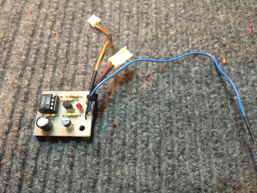
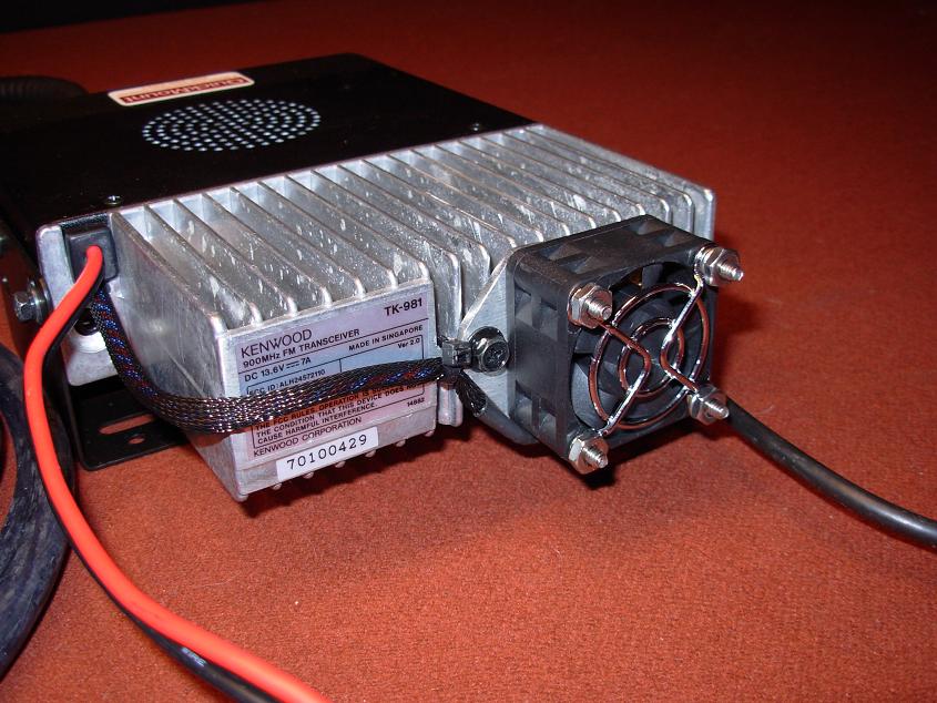
- We now need to add a cooling fan to our radio. For a cooling fan I simply use a 40mm cooling fan, with a Ball Bearing and Brushless motor which is mounted to the rear heatsink. The fan is triggered on when the PTT is pressed and stays on for ~2 minutes. The circuit I used for the fan switches on the fan when triggered high and uses a 555 timer circuit and 2N2222 transistor to switch the NEGATIVE lead of the cooling fan on- this is better then switching the positve lead of the cooling fan if you want to avoid any chance of fan noise/hash. For a very simple and easy to build fan control circuit see the "Downloads" section of this website for N4MW's fan control circuit. You CANNOT run this radio at 45 Watts without a cooling fan, you have been warned!
- We can now, using KPG-49D re-adjust the power out and test our radio. This is probably the most important step and is critical for the proper operation of the radio at 45 watts!!!
In KPG-49D Versions 4.01, 4.02, and 4.20 (Windows based version) read from the radio and go into "Test Mode". From there adjust the power output on 902 MHz for 45 Watts and then adjust the power output at 927MHz (Talkaround) for ~35 Watts using a high quality Wattmeter such as a Bird or Telewave unit into a 50 Ohm dummy load- I would not recommend running this radio much above 45 to 50 Watts as you are pushing the envelope of what the internal components are able to tolerate! You can also readjust and do a full alignment on the radio setting the maximum deviation, QT/DQT Deviation, Modulation Balanced, etc...