Kenwood TK-941L
The Kenwood TK-941L never actually existed; it's a name I concocted after setting up a simplex Echolink node and needing a TK-941 that could run 10 Watts at continuous duty without a fan and without burning up. If you are building a repeater and need an exciter that runs 5-10 Watts, a link radio for your repeater system, an Allstar or Echolink node- without the use of a cooling fan then this project is for you!
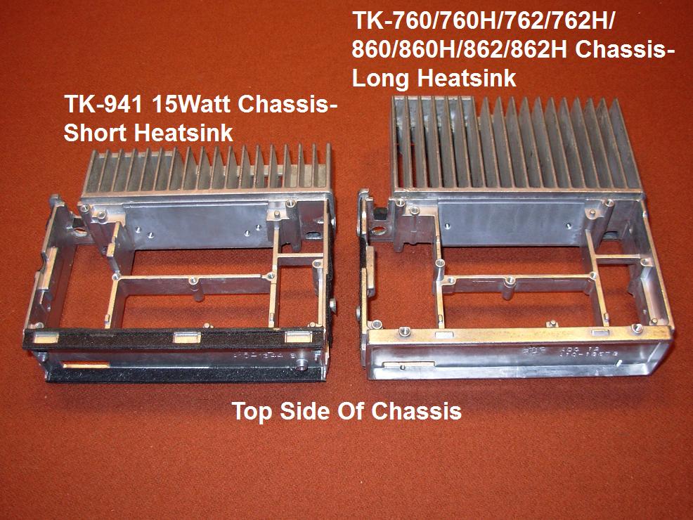
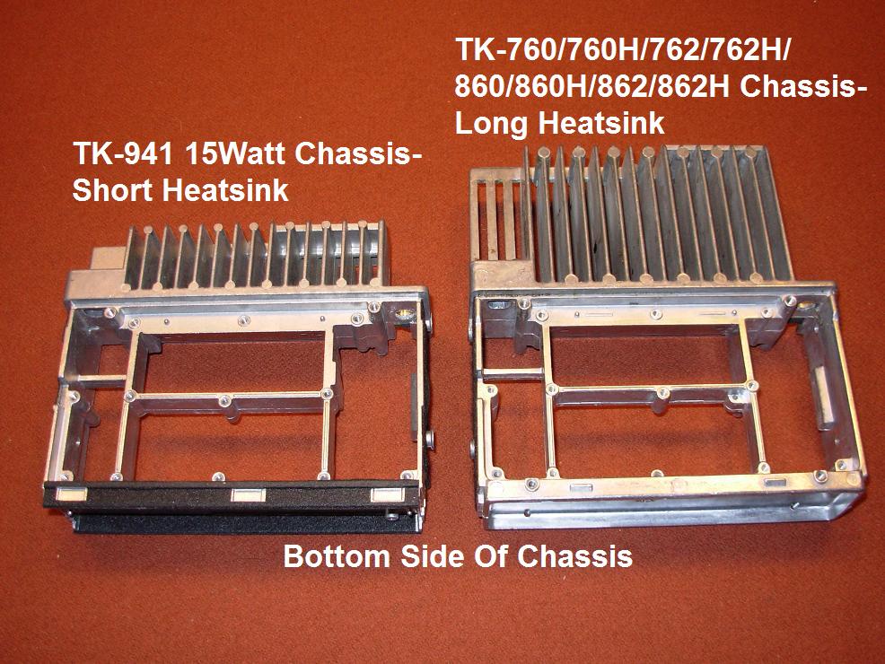
The TK-981H and TK-981HH were founded when I realized that the long heatsink of the TK-x80H, TK-x60HG, and TK-x62HG radios offered additional cooling and endless possibilities. The TK-941, unlike the TK-981, does not have siblings with long heatsinks. Radios in the Kenwood family that do have long heatsinks and are similar in mechanical structure to the TK-941, but not identical, are the TK-760/760H/762/762H/860/860H/862/ and 862H. The chassis from one of these aforementioned radios has a long heatsink with greater surface area that allows it to conduct heat away from the hybrid module in the TK-941 very well.
Transplanting the TK-941 into the long heatsink chassis of one of the above listed radios is not simply a matter of removing the TK-941 main board and display and dropping it in place, it will require a little drilling, cutting, and filing- all easily accomplished in a couple hours.
You will need the following Tools:
- 40-50 Watt Pencil Tip Soldering Iron with Solder Wick
- Phillips Head Screwdriver
- X-ACTO Knife
- 7/32" Round File (Rat Tail File)- any length
- Flat Bastard Cut File
- Smooth or 2nd Cut Flat File
- File Card and Brush (Allows Cleaning of Files)
- Hand Drill (Corded or Cordless)
- 5/64" Drill Bit
- 3mm x 0.5mm Thread Pitch Starter Tap (Finishing/Bottoming Tap Optional)
- #39 Drill Bit (For Above Mentioned Tap)
- Hacksaw Blade (No Handle Needed)
- Duckbill or Needle Nose pliers
- 1/8" Foam Tape or 1/8" Foam
- Heat Sink Thermal Compound (Zinc Oxide)- This is NOT optional
You will need the following Parts:
- One complete TK-941 radio that is tested and working
- One complete TK-760/760H/762/762H/860/860H/862/862H- MAKE sure that you do not have a radio with a "G" in the name as these are the same layout as the TK-981 chassis and will NOT work on the TK-941!
BEFORE WE START:
Make sure that you understand that this modification is NOT for people who lack an understanding of how to work with hand tools, small parts, or fabrication. Know YOUR limitations and don't try to do this modification if it is beyond your current skill level. YOU HAVE BEEN WARNED!
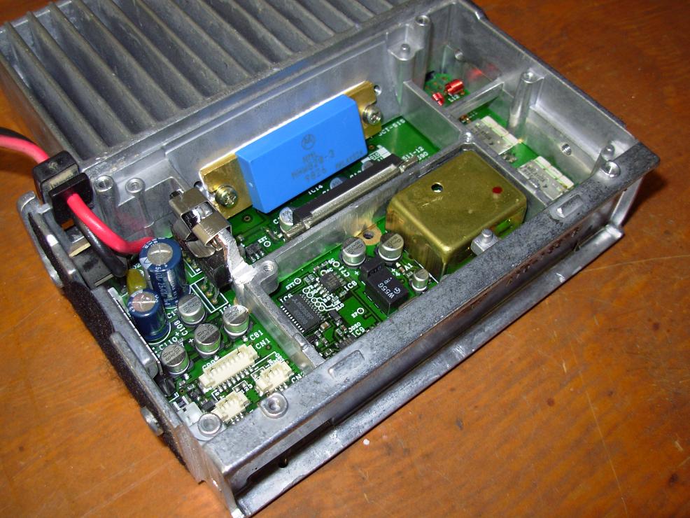
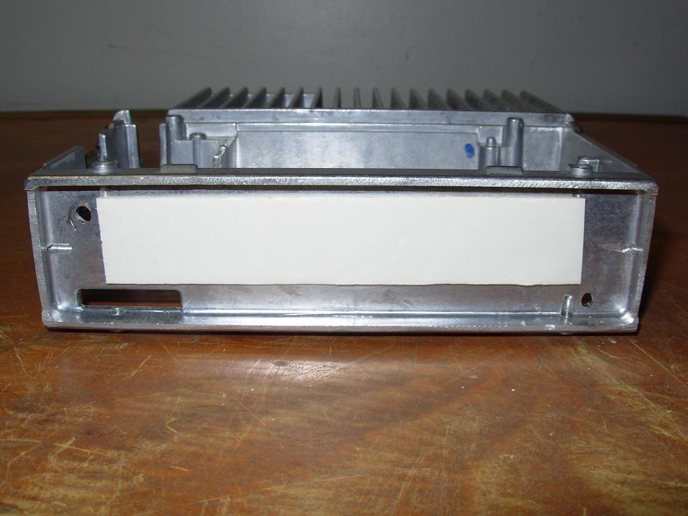
- The first step is acquiring a TK-760/760H/762/762H/860/860H/862/ or 862H long heatsink chassis. These long heatsink chassis are not available from Kenwood, so you will have to find one via the used market. You are looking for a working or non-working TK-760/760H/762/762H/860/860H/862/ or 862H- as long as the chassis, top, and bottom covers are in one piece thats all you need- I have had great luck on eBay contacting sellers and asking if they happen to have one laying around- usually $10 to $45 will get you what you need including shipping. Pictured below is the main reason we are going to go with the longer heatsink, the surface area of the TK-76x/86x series chassis is much greater allowing for better cooling of the PA module.
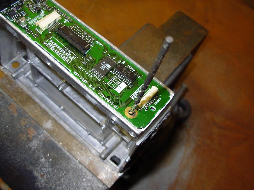
- I am going to skip all the pictures involved with disassembling the radio. As an added note if disassembly of your TK-941 is terribly difficult for you, then stop, this project is definitely not for you! We need to remove the top and bottom cabinet covers of the radio (you will NOT be re-using them), and also remove the speaker, front panel with LCD display. Removal of the front panel with LCD display will require you to unplug the ribbon cable from the control board; the board with the mic connector on it which is mounted to the front of the radio chassis. Removal of the control board on the front of the radio will require you to unplug the ribbon cable which is connected to the front bottom of the main RF board- be very careful in doing this! We also want to remove the retainer clip that holds the audio PA securely to the chassis, and remove the retainer clip that holds the 7808 voltage regulator and APC drive transistor to the TK-941 chassis. The RF shield that covers the VCO on the top inner part of the radio will need to be removed and reused. Flip the radio over and remove the RF shield that covers the bottom of the main RF board on the radio. AT this point we also want to remove the 2 screws holding the coax pigtail to the rear of the chassis and de-solder the coax pigtail and remove it, be careful in doing this, as too much heat can remove the trace from the main board. Save all screws you have removed and keep track of what screws went where; we will be re-using them in this project.
You will need to remove the 2 screws that hold the PA module (Motorola MHW820-3) to the rear heatsink. After removing the PA screws remove all screws holding the main RF board to the chassis and save. Carefully and slowly remove the main RF board from the chassis and wipe clean all thermal compound from the PA Module- leave the module intact (do not remove it from the main board) and use caution when cleaning off the thermal compound as the legs of the PA module bend easily!
- You WILL be re-using the following from your TK-941:
- Main RF Board and PA Module (which should still be attached) and 4 screws
- Power Cord (which should still be attached to the main RF Board)
- Top of radio RF Shield and all 6 screws
- Bottom of radio RF Shield and all 8 screws
- Speaker and plastic speaker support
- Coax Pigtail and 2 screws
- Front Plastic Panel with Front LCD Board and ribbon cable
- Front Control Board (that was attached to the radio chassis) with ribbon cable that went to Main RF Board and 2 screws
- Audio PA Metal Clip
- 7808 Voltage Regulator and APC Transistor Metal Clip
- This step will require disassembly of your donor TK-760/760H/762/762H/860/860H/862/862H radio. You can disassemble the donor radio much like the TK-941 we disassembled. You WILL be re-using the following parts from your donor radio:
- Long Heatsink Chassis
- Top and bottom cabinet covers and ALL 8 small black screws
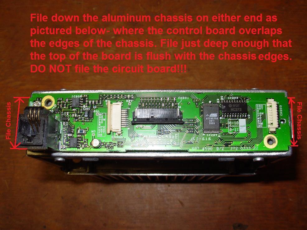
- The first step in our modification process is to get the front control board attached to our donor chassis. On our donor radio (the original TK-76x/86x) the control board/LCD/front panel are integral and attached by the front panel plastic clips, on our TK-941 this is not the case. We need to attach the control board to the chassis and to do this we must file down the chassis and board so they fit as one. Set the control board down on the front of the donor chassis (it helps to have the chassis vertical) and take note of the area where the vertical control board edges overhang the chassis- mark the area on the chassis where the control board overhangs on the chassis with an ink marker and file the aluminum chassis down slightly- so that the control board just rest's flush with the top of the aluminum chassis edges; this means you are filing approximately 1-2mm deep and no more! DO NOT file down any part of the control board! The goal is to have the control board rest on the area of the chassis you just filed- that is the only part of the control board that will be touching the chassis. You will notice at this point that the control board will still not fit due to the corners being square (and the inner chassis casting being round)- we will remedy this in the following step.
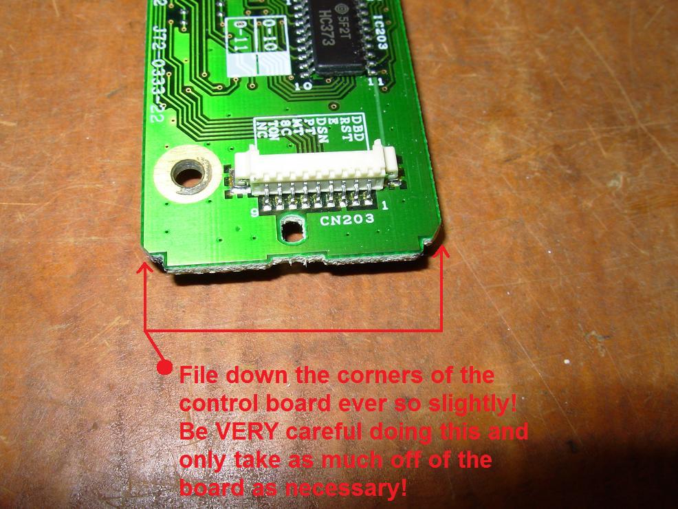
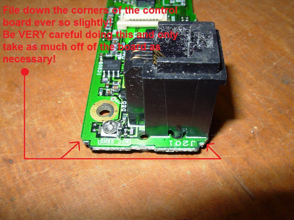
- In this step we need to slightly knock down the corners of the front control board so that they fit inside the front well of the donor chassis. Big warning here: DO NOT go overboard in filing the edges of the board; only take off enough of the control board so that it fits inside of the well of the donor chassis.
- We can now check the fit of the control board in the front of the long heatsink donor chassis. The panel should rest flush with the front top of the chassis edges; it should NOT be sunk below the edges of the front aluminum chassis.
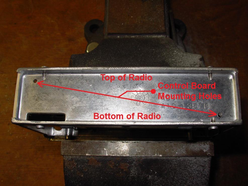
- This step will be drilling the holes so that we can secure the front control board to the radio chassis. Make sure you pay attention to the orientation of the top of the control board and insure it is oriented with the top of the chassis. Using a 5/64" drill bit and with the control board on the front of the radio insert the drill bit on one of the two mounting holes on the control board. Spin the drill bit by hand while pressing down so that the bit makes a mark on the chassis (so we know where to drill holes) - repeat this for the other hole. If you have a transfer punch set then you can use that in lieu of the drill bit.
- After having marked the front chassis in the previous step using our drill bit there should be two spots where the control board mounting holes line up, use the 5/64" drill bit and drill two holes into the front of the chassis. Take the original mounting screws and thread them into these holes to test for fit.
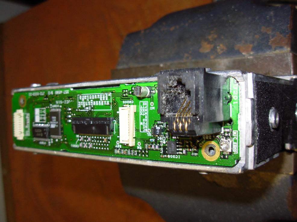
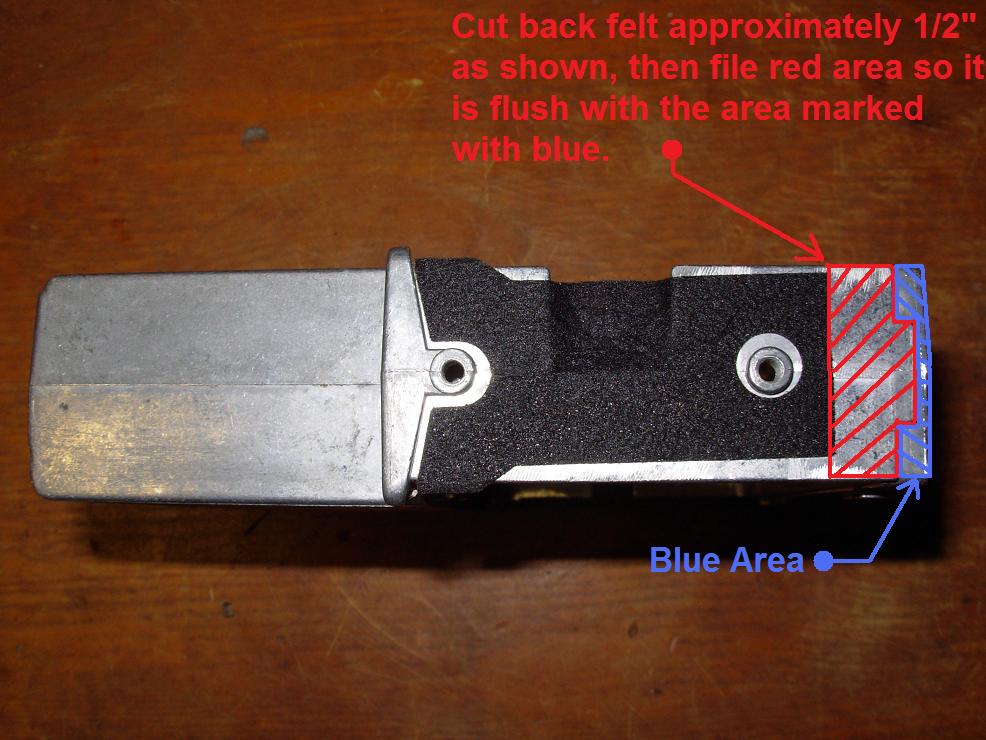
- We will now need to do more filing of the chassis so that we can mount the front control panel to the chassis. The control panel is held in place with two flat head Phillips screws. The tabs on either end of the front plastic panel require that the chassis be filed down for clearance. With the control board set aside in a safe spot, mount the chassis in a vice. Choose either side of the donor chassis and file down both sides as shown in the picture below.
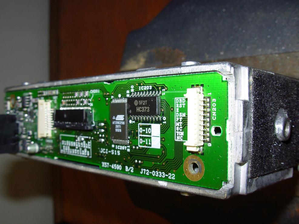
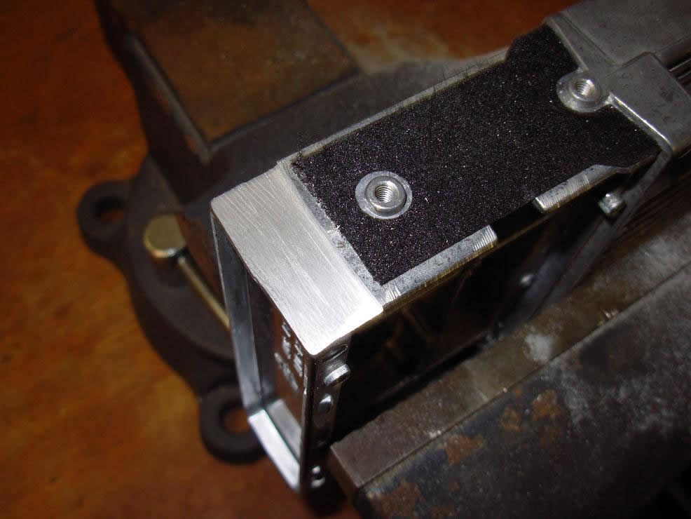
- At this point, you should have the donor radio chassis filed down on both sides so that it looks like the chassis pictured below.
- Now that we have either side of the chassis filed down we need to mark and drill holes for mounting the front control panel to the chassis. Place the control board on the front of the chassis, and then place the front control panel over it. With the control board in place and the plastic front control panel over it and in place (the mic port should be lined up properly); take the top cabinet cover of the donor radio and place it on the top of the chassis; this will set our front panel spacing and align the front panel properly with the chassis- ensure there are no gaps between the front panel and top cover.
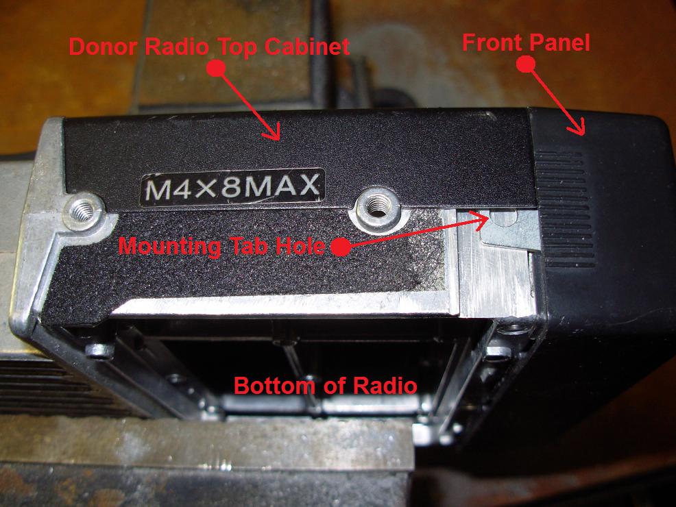
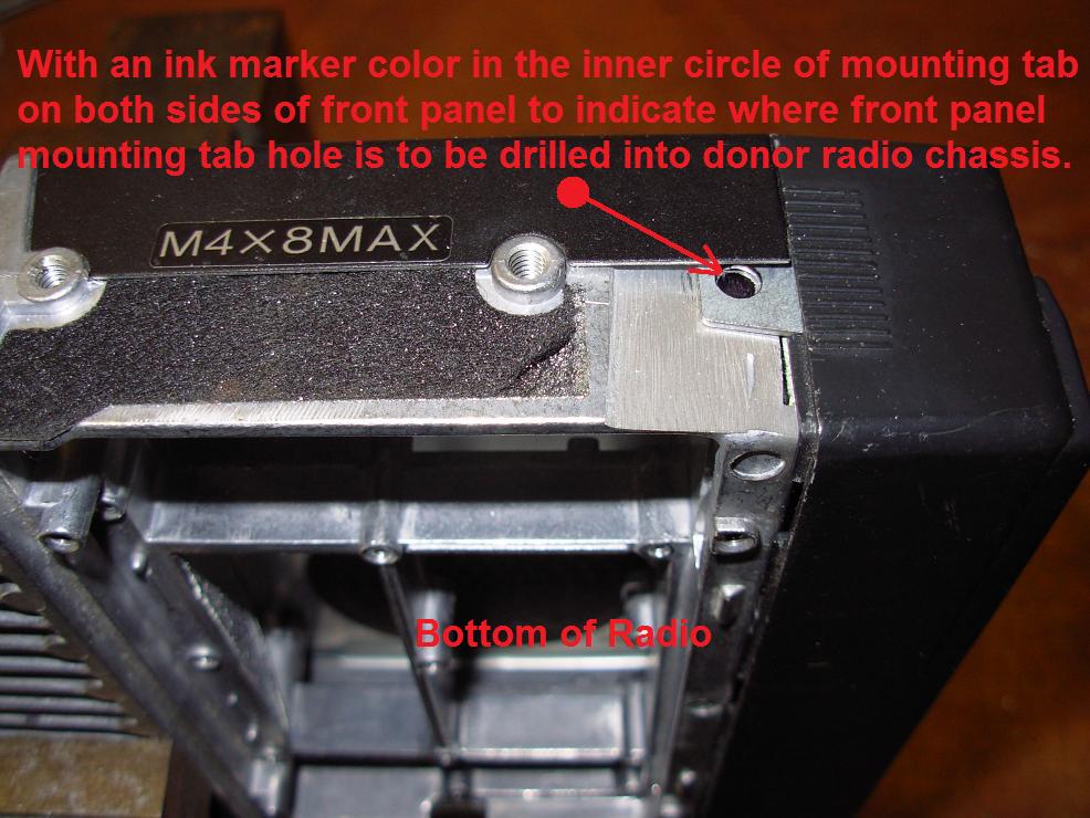
- In order to know exactly where to drill our front panel mounting holes in the side of the chassis, mark the inner circle of the mounting tabs of the front panel with an ink marker. You may have to carefully, and without moving the front panel, lift the top cabinet up ever so slightly to completely fill in the mounting tab inner circle with ink.
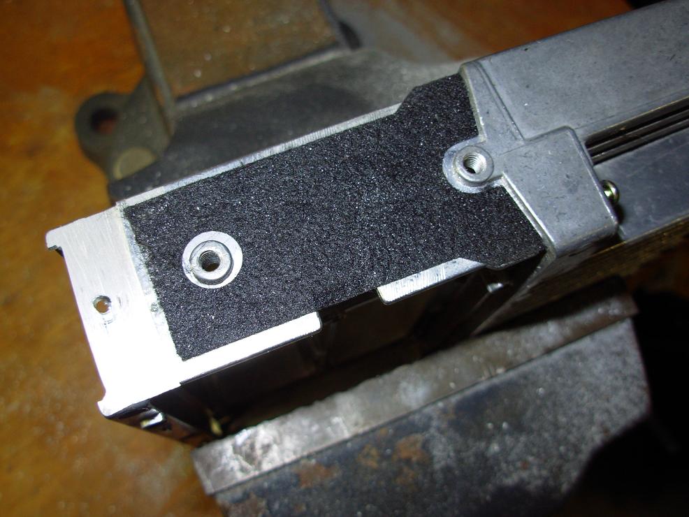
- On this step you can drill out the center of the ink circles you made in the previous step with a 5/64" drill bit. After drilling you will have a chassis with holes as shown below.
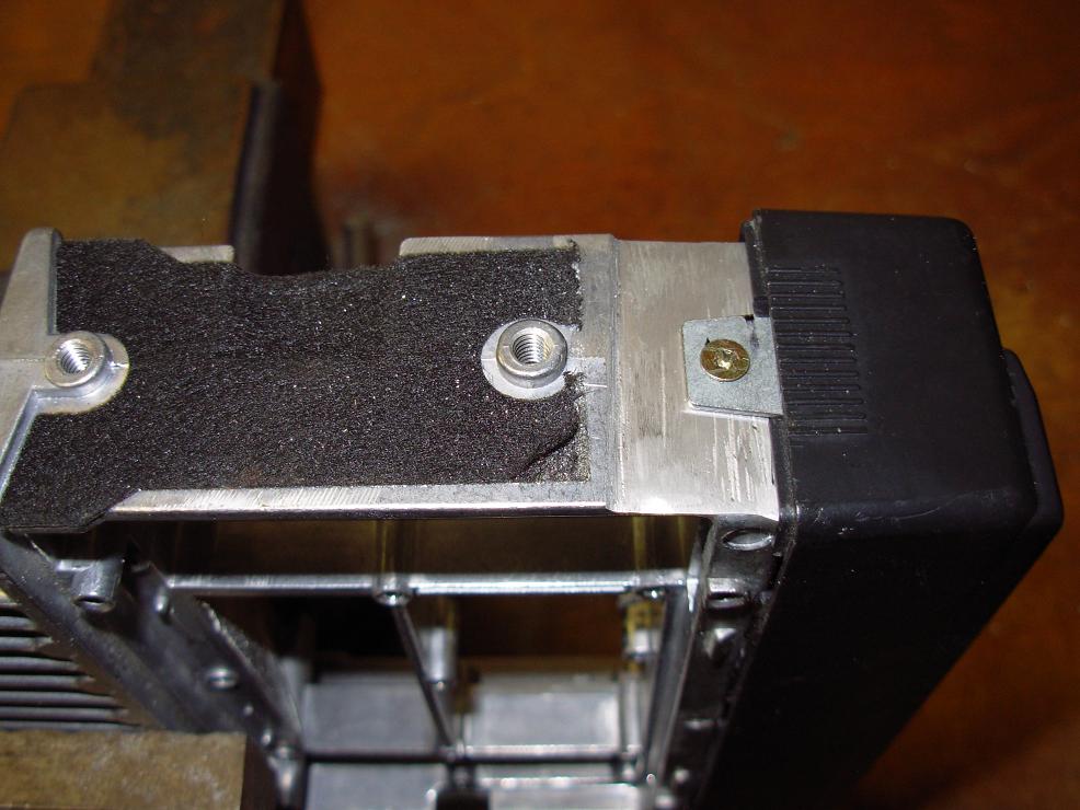
- You can now test the fit of your front panel by using the original flathead Phillips mounting screws and threading them into the chassis. The chassis material is so soft that a little umph will get them in- be careful and do not over tighten them as you can strip out the holes easily. After testing the fit of the front panel assembly remove the front panel and control board; set them aside in a safe spot.
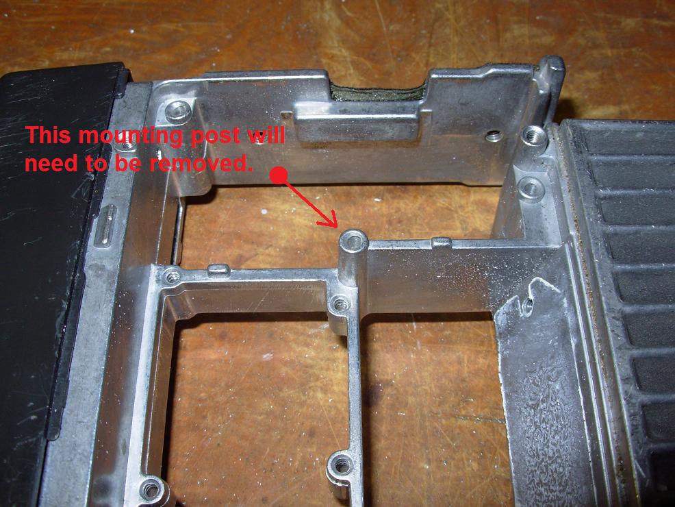
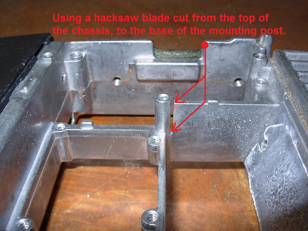
- We will now need to modify the chassis to allow the top VCO shield to fit in its original location. We cannot use the original donor top VCO shield because it does not have mounting tabs to hold the predrive RF module against the chassis as a heatsink. There is one mounting post on the chassis that we will need to remove. Using a hacksaw blade and no handle, saw down from the top of the mounting post as shown, to the bottom of the mounting post. Once the cut has been made you can use duckbill pliers and snap the mounting post off. Once removed file down the surface where the mounting post base was and the side of the chassis so that it is smooth to the touch.

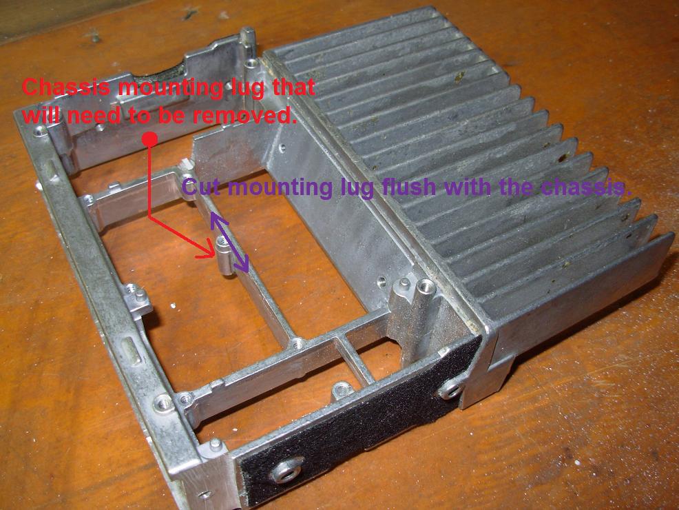
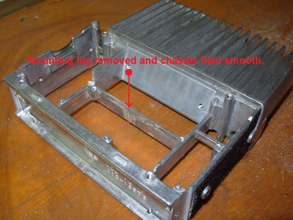
- The next step will be to cut flush a mounting lug that held the donor chassis original RF shield in place that interferes with the TK-941 board. Using our hacksaw blade we are going to cut off the mounting lug as pictured below. The cut will involve cutting in a direction in which the blade is parallel with the front of the radio (in the direction shown with the purple arrow below). Once the mounting lug has been cut flush, file smooth any roughness.
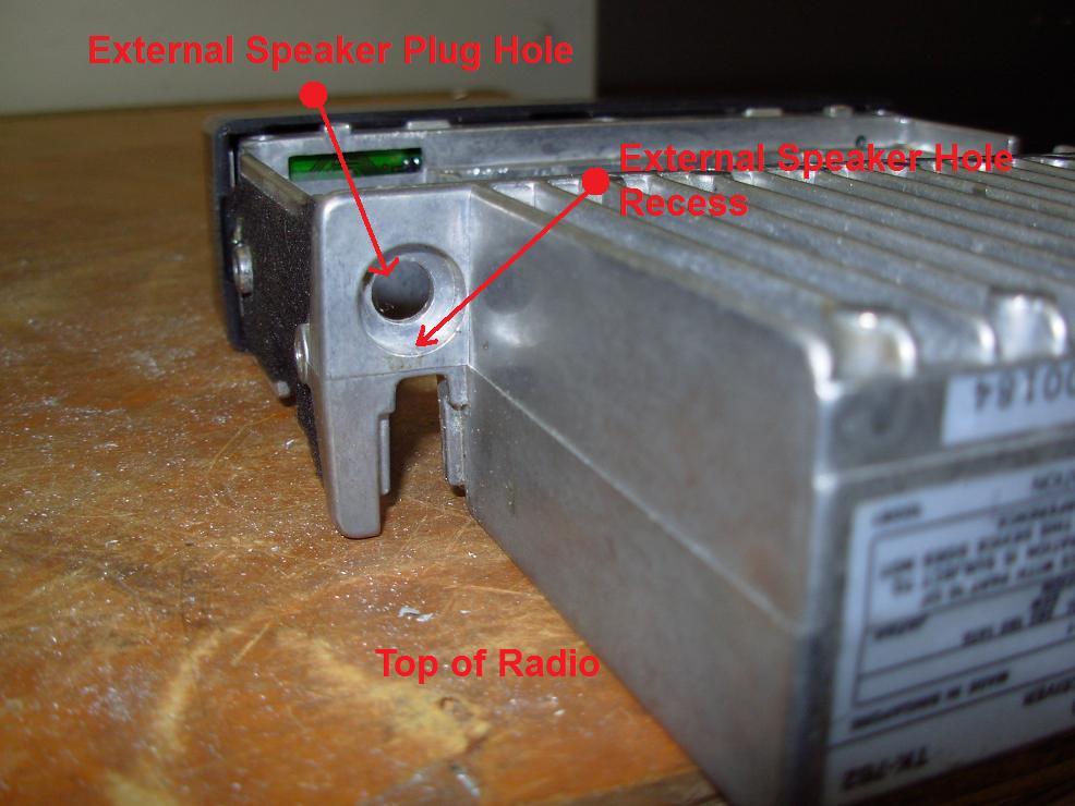
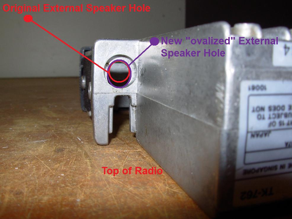
- The main RF board is close to being able to fit in our donor chassis but we will need to do a little filing to the external speaker hole so that the main RF board will sit flush with the chassis casting. Using our 7/32" Round File (Rat Tail File) we will ovalize the existing hole so that the RF board fits. With the chassis upside down resting on its top, file down to the bottom of the recess in the casting where the hole is for the external speaker plug.
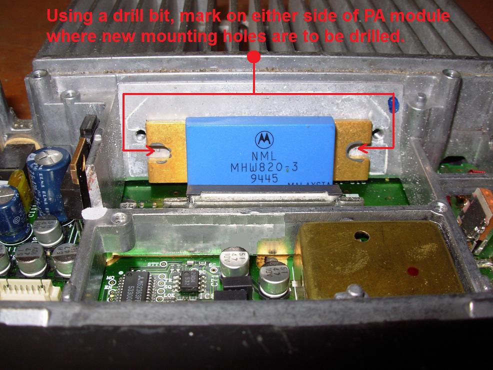
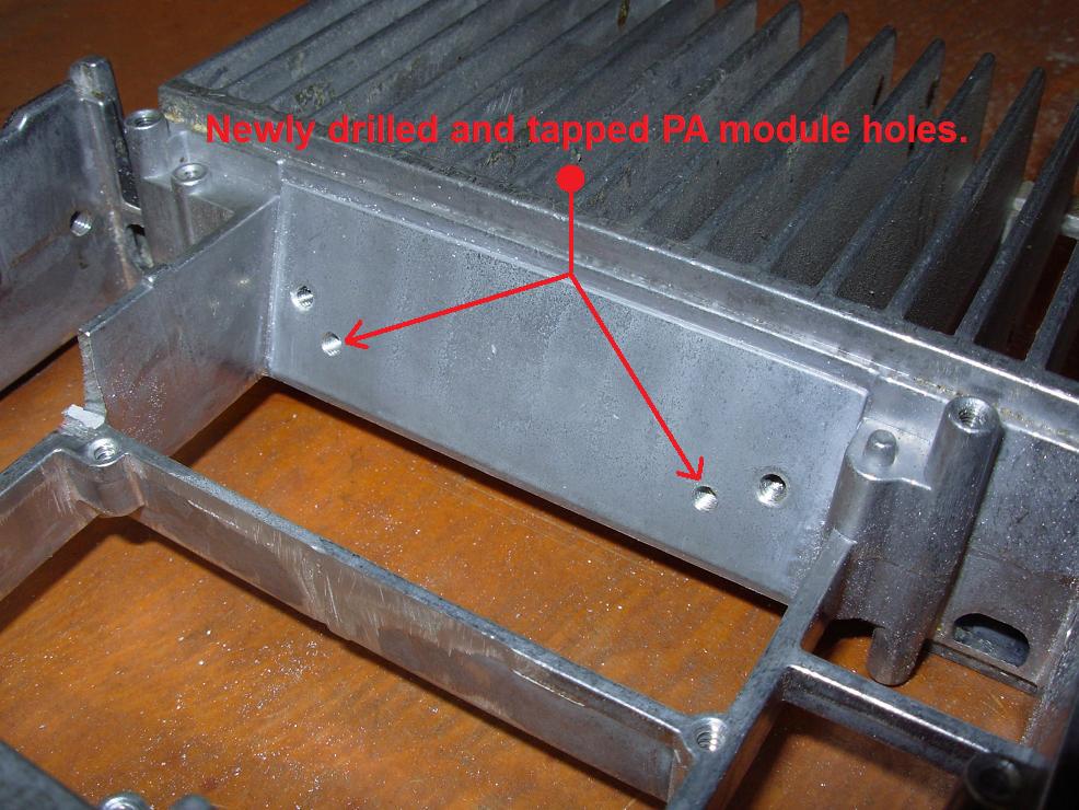
- The original donor radio PA hybrid module is much larger than the TK-941 Motorola MHW820-3. Because of the size difference we must drill and tap the chassis so that the original screws that held the MHW820-3 PA module in place can be used to hold it securely against the new donor chassis for efficient heat transfer. Before proceeding, clean off any metal shavings from our previous drilling, cutting, and filing. Ensure there are no metal shavings anywhere on the chassis at this point. Once the chassis has been thoroughly cleaned you will need to have your #39 drill bit ready. Fit the main RF board into the chassis and check for proper fit. If there is any part of the donor chassis that is not allowing the board to sit properly then spend a moment to file or cut what is needed. If your board fits correctly then using a #39 drill bit spin it in the tabs of the PA hybrid module on either side of the module so that it leaves a mark in the chassis. Due to the angle of the module and the shape of the chassis you will not be able to use a transfer punch to mark the mounting holes that will need to be drilled. Once either side of the PA module mounting tab has marks on the chassis clear enough to see, remove the RF board and set it aside in a safe spot. You may want to take an ink marker and make dots where the marks were left from your drill bit so that the marks are more visible. Use your #39 drill bit and drill 2 holes in the chassis where you made your marks. Ensure you do not drill through the backside of the chassis heatsink; but are still deep enough to allow the PA screws to thread in all the way to the chassis with the PA module in place.
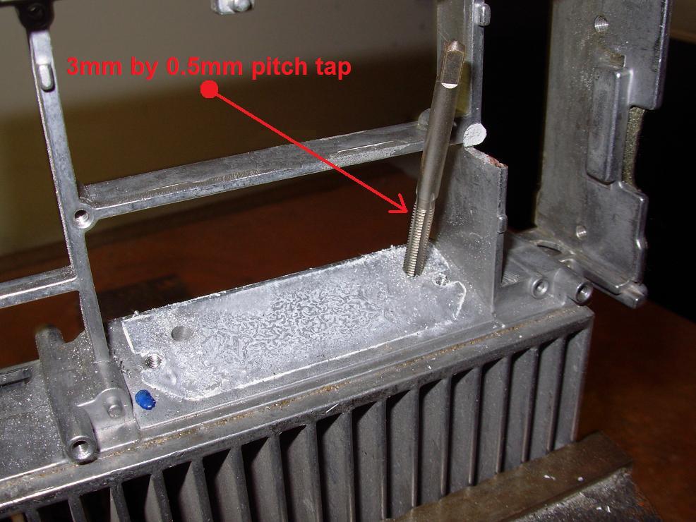
- Once the two holes are drilled for the PA module in the above step use a 3mm x 0.5mm thread pitch starter tap and tap our freshly drilled holes. The chassis material is very soft so be careful and get the tap started straight. You can go over the threads with a finishing/bottoming tap if you have one but this is optional and not necessary.
- After having tapped the holes for the PA module your chassis should look like the chassis pictured below. It is a good idea at this point to wash the entire chassis in warm (not hot) soapy water and scrub clean any metal shavings or debris. Ensure the chassis is thoroughly dry and free from debris before proceeding forward.
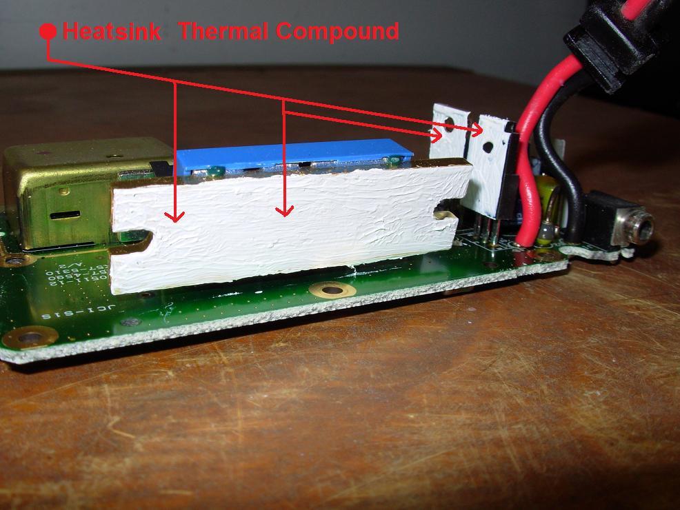
- We are now able to do the finishing touches to the main RF board in preparation for its final resting place in the long heatsink donor chassis. Lightly, but thoroughly coat the back of the PA Module, APC transistor, and 7808 voltage regulator with heat sink thermal compound.
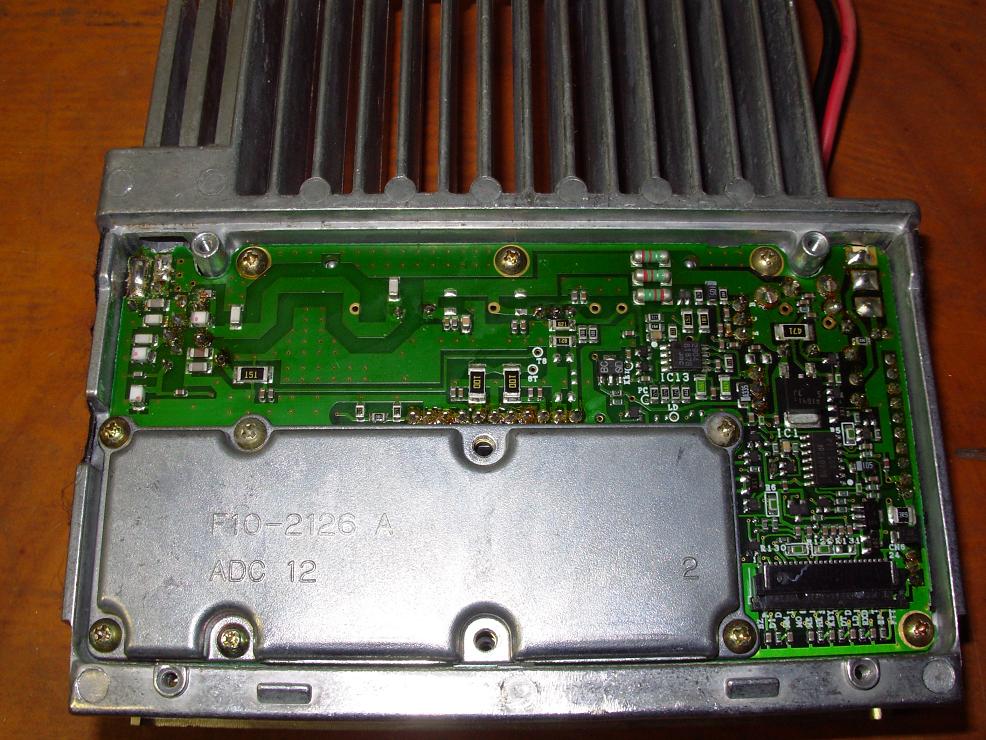
- With the PA Module, APC transistor, and 7808 voltage regulator lightly coated in heatsink thermal compound carefully insert the main RF board into the donor chassis. Now that the main RF Board is resting in its new home we need to install all the mounting screws to secure it. Ensure all the screws (Qty 4) that hold the main RF board in place, on the bottom of the radio, are installed. Ensure that the original RF shield is installed along with 6 of the original 8 screws- you will not be able to use 2 of the original screws (as pictured). On the top side of the radio be sure to install the 2 screws that hold the PA module in place.
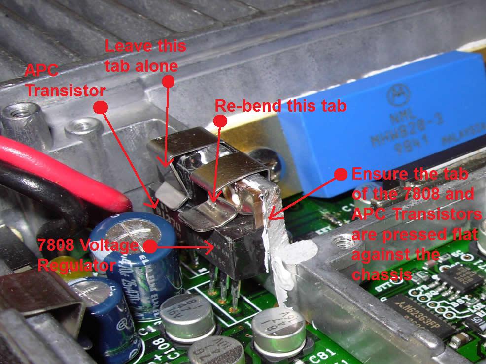
- We need to install the retaining clip on the APC transistor and 7808 voltage regulator. Before installing the retaining clip we need to ensure that the APC and 7808 voltage regulator tabs' are pressed flat against and parallel with the chassis, you may need to slightly bend the legs of both components to ensure they are properly pressed against the surface of the chassis and are parallel with it. Once these components are properly located we will need to re-bend the tab on the side that presses against the 7808 voltage regulator. You do not need to re-bend the tab on the APC transistor side. Using duckbill or needle nose pliers re-bend the retaining clip on the side that holds the 7808 voltage regulator in place. Ensure that the clip holds the regulator firmly against the chassis- see picture below.
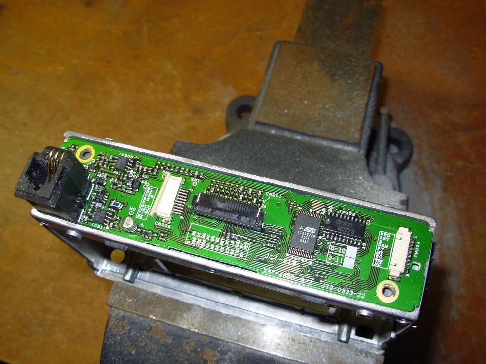
- We should now have a TK-941 that looks like the picture below. The retaining clip for the audio amp will need to be installed as well as the RF shield for the VCO- both are not shown installed in the picture below.
- We are now ready to install the control board and front panel. Before doing so we need to ensure that the back side of the control board cannot make contact with the aluminum chassis. To ensure that the board cannot touch the chassis, place a strip of 1/8" foam tape, 1/8" foam, or any insulating material so that a good majority of the front chassis is covered. The goal is to have as much of the front of the chassis covered so that contact with the backside of the control board is not possible.
- After applying our 1/8" foam tape, 1/8" foam, or insulating material install the control board with 2 screws and plug in the ribbon cable to the main RF board. You can now install the front panel of the radio and plug the ribbon cable into the control board. Once the control board and front panel are installed you can re-install the coax pigtail, speaker, speaker bracket, and top and bottom covers. You now have a finished radio!