TK-481 Troubleshooting Section
"Help! My TK-481 or TK-981 scans automatically and I did not press the scan button!
I cannot lockout a nuisance repeater, this is frustrating!"
This is a problem that arises when the TK-481 and TK-981 are not programmed correctly!
Programming "Epic Fail" Method 1
The first common mistake in programming a TK-481/981 is to put all the repeaters in your area in the SAME System (i.e. System 1 Groups 1-23 as an example) and set the Scan type in KPG-49D as "FIX SYSTEM SCAN". If you program the radio this way, the radio is only going to scan the SELECTED Group in EACH System, and since you only have one system programmed, and the Scan type selected in KPG-49D is as "FIX SYSTEM SCAN", this means that you are not really scanning at all.
Programming "Epic Fail" Method 2
The second most common mistake in programming is the belief that all the repeaters in your area should be in the same System or from people who love Motorola and want to make a Kenwood radio work like a Motorola radio and therefore create scan lists- a Kenwood scan list is not the same as a Motorola Scan list. This mistake in programming means that people program all the repeaters located in their area in the SAME System, increasing Groups, and then in KPG-49D select "LIST TYPE SYSTEM SCAN" and create a scan list. If you program the radio this way, the radio is going to scan all the time, without you selecting scan, unless you set Group Lockout to Yes and/or No depending on what you want scan to do.
The above examples of Epic Programming Fails are not the ways to program a Kenwood TK-481 and TK-981.
The way to properly program a Kenwood TK-481 and TK-981 is as follows:
Program all the repeaters in your area in their OWN System (System 1 up to System 32) and the SAME Group. Set the Scan type in KPG-49D as "FIX SYSTEM SCAN". Then assign a front panel button to "SCAN" and also assign another button to "SCAN DEL/ADD", and LEAVE the Group Lockout set to "YES" (which is the default setting). If you program your radios this way you are going to LOVE your 481 and 981 more than ever!
Here is an example of how to program a 481/981, these locations will look familiar if you happen to live in California in the SF Bay Area:
Oakland Repeater is programmed in System 1 Group 1
Mt Vaca Repeater is programmed in System 2 Group 1
Sunol Repeater is programmed in System 3 Group 1
Calistoga Repeater is programmed in System 4 Group 1
Los Gatos Repeater is programmed in System 5 Group 1
San Jose Repeater is programmed in System 6 Group 1
Pacifica Repeater is programmed in System 7 Group 1
Cupertino Repeater is programmed in System 8 Group 1
Redwood City Repeater is programmed in System 9 Group 1
Vacaville Repeater is programmed in System 10 Group 1
...continue programming every repeater in your area in INCREASING System numbers and the SAME Group. Ensure that you have Scan set to "FIX SYSTEM SCAN" (which is the default) in KPG-49D; the radio will scan when the scan button (SCN) is pressed, it will stop scanning when:
- The radio encounters a busy channel.
- You manually stop scanning by pressing the Scan button- make sure you have the radio "SCAN REVERT" programmed as either "LAST CALLED" or "SELECTED+TALKBACK".
Remember the radio will Scan every System, and ANY SELECTED Group in each System- once again ANY Group can be selected- this means you get a lot of versatility! This does not limit you to just 32 frequencies; you can program the radio with multiple states or areas (as I have done on my own personal radios)- but you can only scan 32 frequencies at any one time.
If you have a linked repeater system in your area- you could program the linked repeater system in the SAME System and INCREASING Groups- and just select the closest repeater to you and the radio will scan just that Group in that System. If you want to block a repeater from being scanned then press the button that you assigned "SCAN DEL/ADD" to and that System will be removed from scanning- pretty easy and painless!
A simple recap of what NOT to do:
- Do NOT program all the repeaters in your area in the SAME System.
- Do NOT use "LIST TYPE SYSTEM SCAN".
- Do NOT use Scan Lists.
- Do NOT think of a Kenwood System as a Motorola Zone; they are not the same. This statement DOES NOT apply to the NX-901 and NX-411 which use Zones and Channels and NOT Systems and Groups.
A simple recap of how to program a 481/981
- Put every repeater in your area that you want to scan in its OWN System and the SAME Group
- Leave the scan setting set to "FIX SYSTEM SCAN"
- Assign a button on the radio such as the "A", "Mon", or "Aux Switch" button as "SCAN DEL/ADD".
- Assign Scan to the "SCN" button.
- If you have a linked repeater system then the best idea is to put each repeater that is linked in ONE System and INCREASING Groups
- If you want to add more repeaters then add to EACH System and the NEXT Group in each System
"Help! I tried to read from a used TK-481 I purchased and KPG-49D or KPG-35D says that the radio requires a password to read from it, what do I do?"
If you tried to read from your TK-481 and found that it is password protected, then simply create a new DAT file and program over it. Do not worry about losing any functions or features in the radio, it's not a Motorola, and therefore you will not lose or gain any features or options. The password protection only works when reading from the radio and not when writing to the radio. When you write a new file to the radio the existing password will be deleted and you will be able to read and write to and from the radio.
"How do I know if I have an original Kenwood TK-481 900MHz antenna?"
The original TK-481 handheld antenna, part number T90-0640-25, has a female SMA connector at the base. The antenna has three grooves in the rubber molding at the base of the antenna, is 150mm long from tip to the base of the antenna skirt (excluding the connector), and has a small red Sharpie Marker (ink) dot next to the female SMA connector (see picture below)- if your antenna does not have a red ink dot, on the metal part of the base of the antenna then your antenna is NOT for 900MHz! Please see attached pictures to help you identify your antenna as one that is intended for use on 900MHz.
The 800MHz antennas for the TK-480 are very similar in their appearance to the 900MHz antennas for the TK-481. The TK-480 800MHz antennas are slightly longer (156mm in total length) then the 900MHz TK-481 antennas and have a black Sharpie Marker (ink) dot next to the female SMA connector instead of a red Sharpie Marker (ink) dot found on the TK-481 900MHz antenna.
The UHF 450 to 490MHz antennas for the TK-380 and TK-385 look a lot like the 800 and 900MHz antennas except that they are slightly shorter (143mm in total length) then the 900MHz TK-481 antennas and have a molded and painted (NOT ink!) red dot at the base of the antenna skirt (on the black rubber molding) and NO red ink dot on the metal part of the antenna near the female SMA connector.
The 900MHz TK-481 antenna is 150mm in total length from tip to skirt base- excluding the female SMA connector.
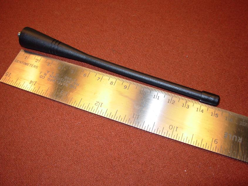
There are 3 ridged grooves near the base of the antenna.
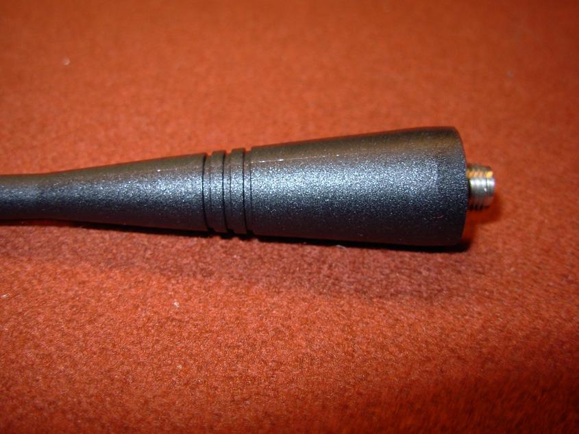
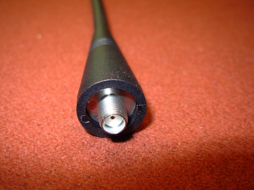
There is a small red ink dot placed on the metal part of the base of the antenna- this dot is placed there by hand at the Kenwood factory to identify it as a 900MHz antenna. The red ink dot can be seen at the 9 o'clock position in this picture.
"Help! My TK-481 has a bad Volume/Power Switch or Encoder, how do I remove them to fix it?"
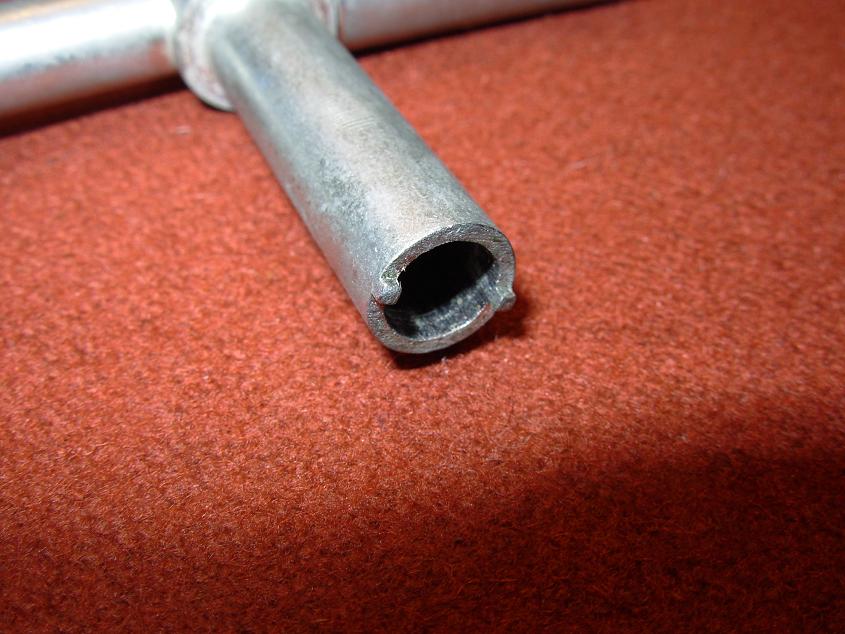
If the Volume/Power Switch or Encoder is damaged or worn out on your radio you can replace them with new parts- but what holds these in place to the chassis of the radio and how do you remove them? The Volume/Power Switch and Encoder are held in place to the top of the radio with what might appear to be a variation of a Castle Nut- Kenwood calls them a "Circular Nut" and removing them can be done several ways. There is a special tool that can be purchased on eBay, for VERY cheap (~$8) that will remove these "circular nuts" very easily and without damage to the nut itself. They are sold on eBay by mainly Asia based sellers and have been labeled a "Repair Tool", simply put; they don't have a real technical name. If you do not want to purchase the special tool to remove these nuts then a Circular Clip (C-Clip) tool also works (use caution as you can damage the brass "circular nuts" very easily using these), or you can make your own using some tubing and a Dremel tool or file.
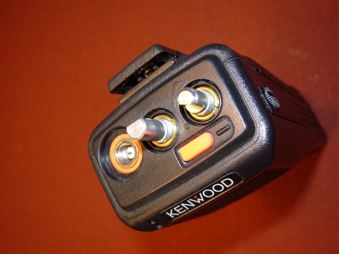
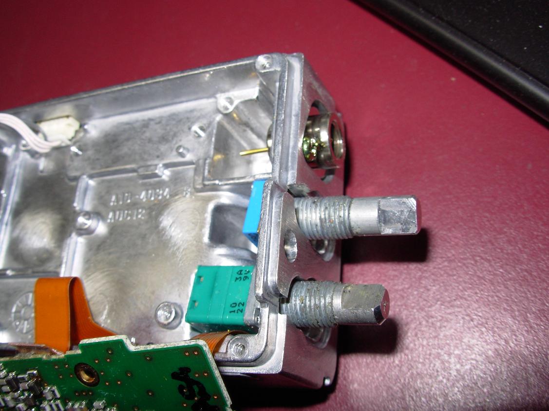
Pictured below is the top of a TK-481 with both brass "circular nuts" on the Volume/Power Switch and Encoder.
The aforementioned "Repair Tool" which can be procured via eBay. This tool is worth its weight in gold if you work on radios.

Close up view of the teeth of the "Repair Tool".
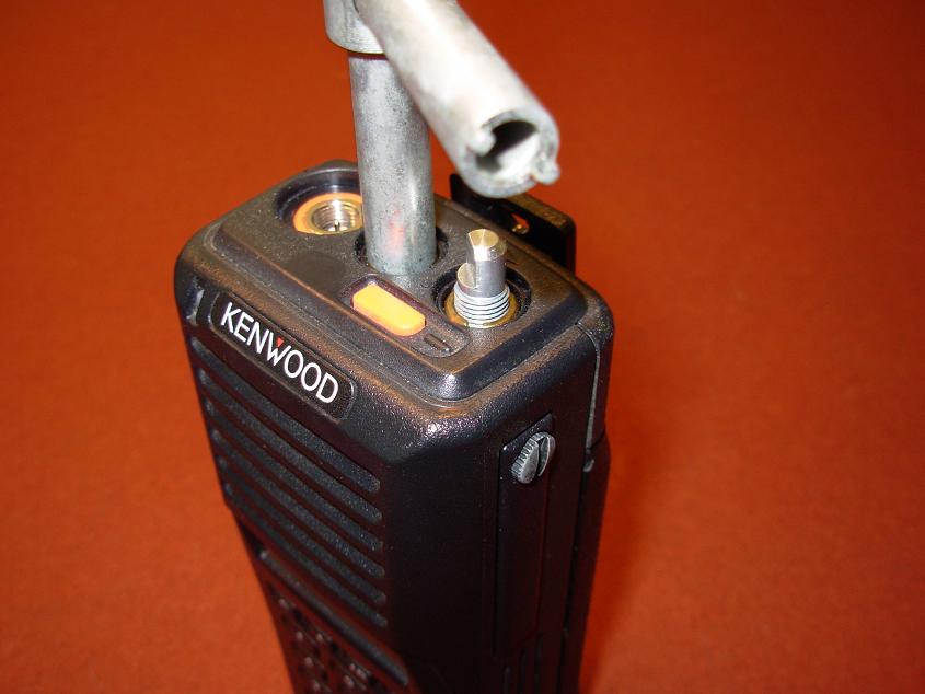
The "Repair Tool" makes loosening or tightening "circular nuts" a breeze!
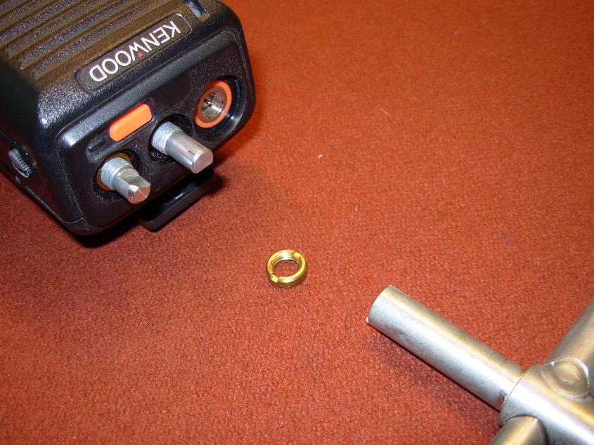
Circular Nut removed with no damage to the threads or "circular nuts".
"Help! My TK-481 has a loose antenna connector- How do I get to it?"
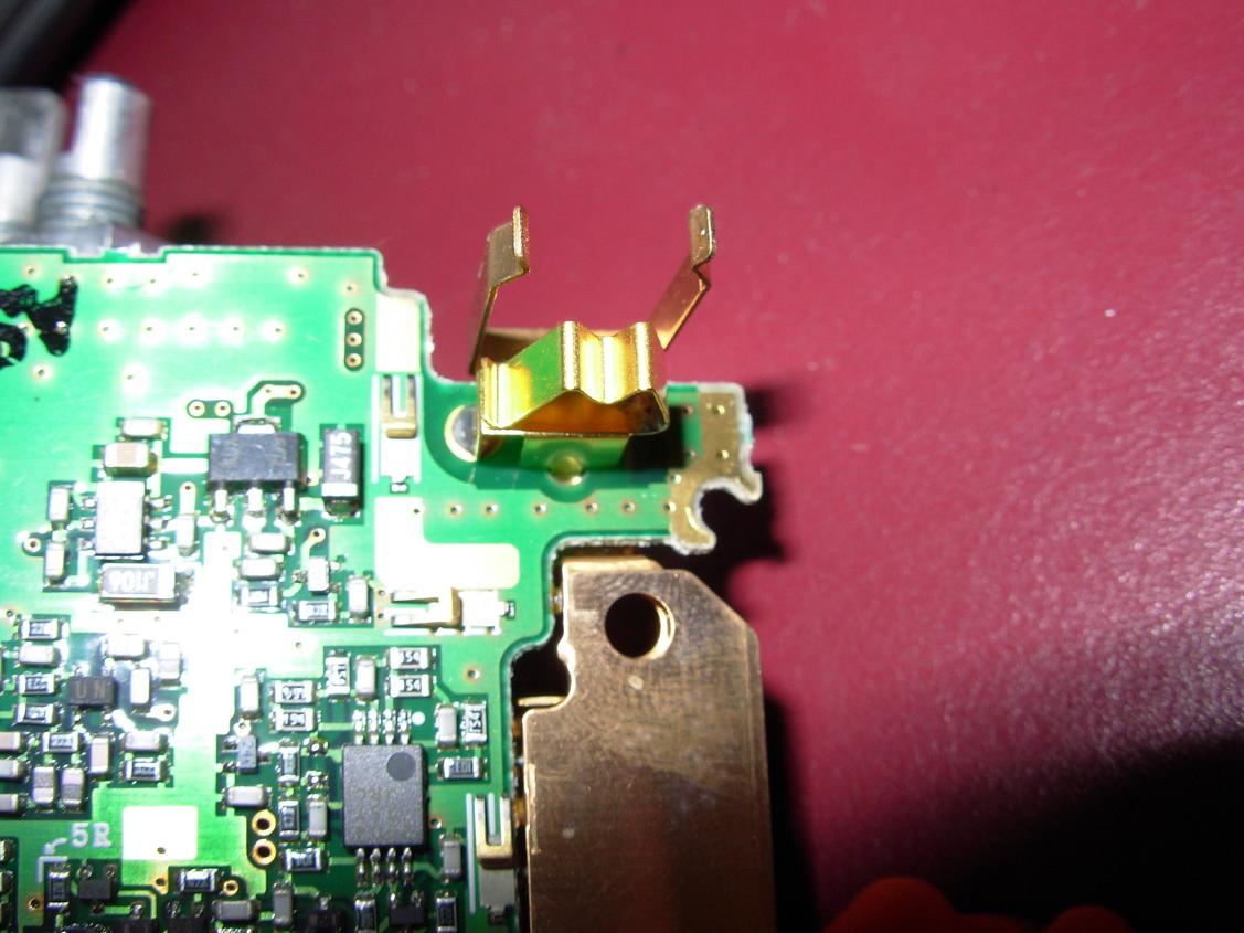
If your antenna connector has come loose inside the radio, fear not, as tightening it does not require disassembly of the entire radio but rather removing just the Panel Assembly (Top Plastic Cover) and using a Phillips Head screwdriver to tighten down the SMA chassis mount connector. The antenna coming loose rarely, if ever, happens but can occur if the radio you own was abused in the past. Use the "Repair Tool" pictured above to remove the circular nuts off of the Volume/Power Switch and Encoder and carefully remove the Panel Assembly to get to the antenna connectors two Phillips head screws. The SMA chassis connector center pin connects to the main RF board by just physical contact with a gold plated "stirrup" that is soldered to the main RF board- there is no direct soldered connection of the center pin of the SMA chassis mount connector to the main RF board!
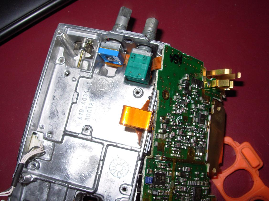
Pictured below is the radio disassembled down to bare chassis so that the connection of the SMA chassis mount to the main RF Board can be seen. Two Phillips head screws can be seen holding the connector in place to the chassis.
The RF "stirrup" can be seen below- the center pin of the SMA connector rests in the center of this.
Another view of the SMA connector mounted to the main chassis.
“Help! My TK-481 will not power up.”
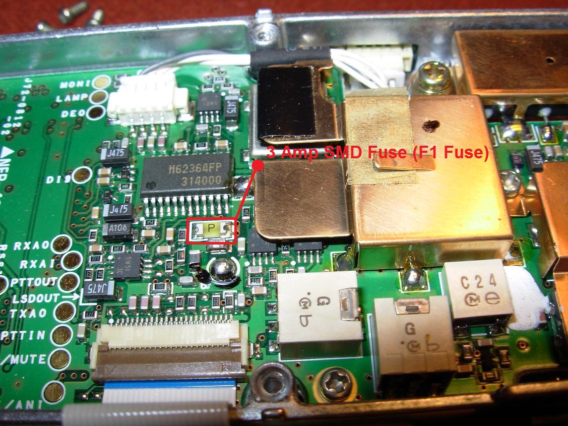
There are several reasons that the radio would not power up but one possibility and something to check is the internal SMD fuse. There is a small SMD 3.0 AMP fuse located on the main board inside the radio. This fuse will blow, as it is designed to, under several different circumstances. The most common cause of this fuse popping is a damaged external speaker microphone, water or coffee inside the radio, or internal damage to the radio from abuse or component failure. Of course its not always easy to figure out the cause; so your best bet is to inspect the radio for the obvious and then change the fuse out. This internal SMD fuse is cheap and somewhat easy to replace. The Kenwood part number for this fuse is; F53-0392-05 and the price was around $1.93!
To get to the F1 3 Amp SMD Fuse, remove the battery and antenna, then remove the 2 screws holding the radio to the plastic front panel. Gently remove main body of radio from front panel.
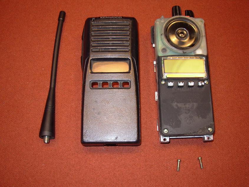
Once the main body of the radio has been removed from the front panel disconnect the speaker from the front control panel and remove the silicone keypad and speaker together as one piece.
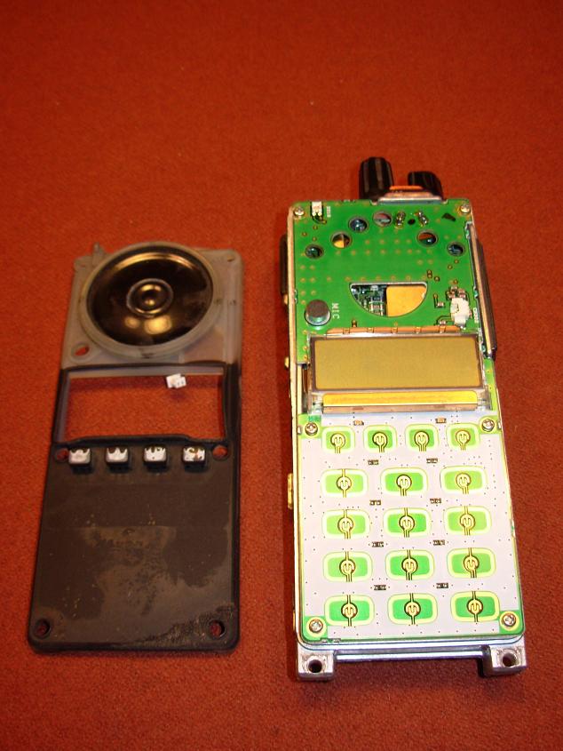
Once the silicone front keypad is removed you can remove the six screws that hold the front panel to the main RF/body of the radio. GENTLY fold open the front panel to allow access to the F1 SMD 3 Amp Fuse.
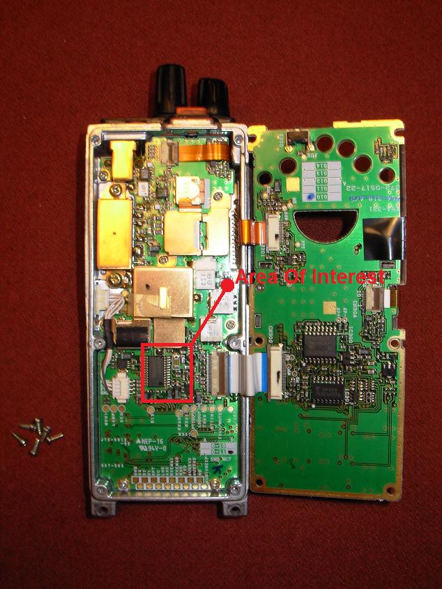
You now have enough access to remove the old (blown) 3 Amp SMD fuse. Replace fuse with Kenwood part number F53-0392-05 and is available from Pacific Coast Parts or East Coast Transistor.