TK-931 Filter Infomation and Changeout
A Quick Note on Why Filter Change Out Should be Done
You can get away with not changing the original filters out if you want a 2uV receiver, which is not very good, changing the receive filters out will yield a 0.20uV receiver or better and is worth doing. If you do change out the receive filters, the receiver of this radio will be better than most 900MHz radio’s out there made by Motorola, EF Johnson, GE, or even the newer Kenwood’s. As an alternative to changing out the receive filters you can re-tune them- see the TK-931 "Filter Re-Tune" section of this website. The receiver in the TK-931 is absolutely outstanding and you are doing yourself a great injustice by not re-tuning or changing them out- it’s worth the extra effort!
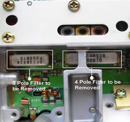
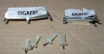
The original filters found in the TK-931 series of radios are the muRata DFC4R938P006BTD, which is a 4-pole filter (that’s the “4R” in the filter part number) and the muRata DFC3R938P006BTD, which is a 3-pole filter (that’s the “3R” in the filter part number). At first glance we see that the filters are centered at 938MHz- close enough to our receive frequency of 927MHz- they work fine…right? One problem exists with this theory- the 6MHz bandwidth rating of the original filters (that’s the “006” in the filters part number). Ceramic band pass filters are quite broad banded, some more than others, BUT they do exhibit attenuation the further away you get from their designed center frequency- in this case 938MHz, hence the “938” in the filters part number. Since these filters have a center frequency of 938MHz and a bandwidth of 6MHz- one can conclude that once you get below 935MHz and above 941MHz the signals start to get attenuated.
Different Filter Types/Manufacturers that Exist
There are several different types of filters that you can install in the TK-931’s. The two main manufactures of band pass filters are muRata and Toko. Both these manufactures make thru-hole and Surface Mount Device (SMD) style filters that are centered at 915MHz both will cover our needed 927.xxxMHz receive frequency.
You CAN use either SMD or Thru-hole style filters- there is no real performance difference between the different styles that I have observed, i.e. use what you can find! Do keep in mind that for obvious reasons the Thru-hole style filters are much easier to install, however, they are getting much harder to find. The SMD style filters are widely available, but they will require a little extra time and effort to install, you will need to fabricate “legs” for them, and be a little more careful in soldering them into place.
You will need two 2-pole filters to assemble into a 4-pole of which you can use either 2 thru-hole style bandpass filters or 2 SMD style bandpass filters- use some creativity in this department! And you will need a 3-pole SMD or thru-hole filter to replace the original 3-pole filter.
The one thing to keep in mind is that you must have the same number of poles as the original filters- if you use a 2 or 3-pole in place of the original 4-pole or 3-pole you might need to add a ceramic disk capacitor of 2.2pF, 3pF, or thereabouts in series to improve the receive sensitivity- as this is a tuned circuit.
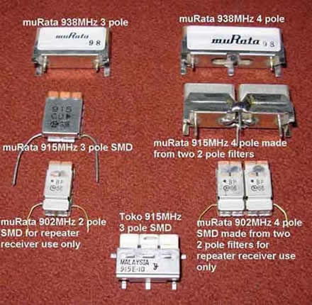
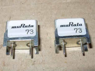
Either filter you choose to use will have either a 25MHz bandwidth (muRata) or 26MHz bandwidth (Toko) because they were originally designed for use in spread spectrum devices, which as the name implies require the passing of signals over a large part of the RF “spectrum”. The 915MHz centered filters will work just great for our application in the 902-927MHz band, because they will work up to our receive frequency of 927MHz and even down to 902MHz.
You will notice in the chart below that there are also filters that were/are available centered at 902.500MHz, these filters are for use in repeater receivers ONLY and should never be used for normal 927MHz use, i.e. do not use them in your TK-931 unless you are building a repeater receiver!
Part # |
MFG |
No. of Poles |
Cntr. Freq. |
BW |
Type |
6DFA-915E-10 |
Toko |
2 |
915MHz |
+/-13MHz |
Thru-hole |
6DFB-915E-10 |
Toko |
3 |
915MHz |
+/-13MHz |
Thru-hole |
4DFA-915E-10 |
Toko |
2 |
915MHz |
+/-13MHz |
SMD |
4DFB-915E-10 |
Toko |
3 |
915MHz |
+/-13MHz |
SMD |
6DFA-902E-10 |
Toko |
2 |
902.5MHz |
+/-12.5MHz |
Thru-hole |
6DFB-902E-10 |
Toko |
3 |
902.5MHz |
+/-12.5MHz |
Thru-hole |
DFC2R915P025BTD |
muRata |
2 |
915MHz |
+/-12.5MHz |
Thru-hole |
DFC3R915P025BTD |
muRata |
3 |
915MHz |
+/-12.5MHz |
Thru-hole |
DFC4R915P025BTD |
muRata |
4 |
915MHz |
+/-12.5MHz |
Thru-hole |
DFC4R902E025BTD |
muRata |
4 |
902.5MHz |
+/-12.5MHz |
Thru-hole |
DFC2R902E025BHD |
muRata |
2 |
902.5MHz |
+/-12.5MHz |
SMD |
DFC3R902E025BHD |
muRata |
3 |
902.5MHz |
+/-12.5MHz |
SMD |
| DFCB2915MLBJAA-RD1 |
muRata |
2 |
915MHz |
+/-12.5MHz |
SMD |
DFC2R915P025BHD |
muRata |
2 |
915MHz |
+/-12.5MHz |
SMD |
DFC3R915P025BHD |
muRata |
3 |
915MHz |
+/-12.5MHz |
SMD |
At this point I would like to add one word of caution: just because the filters will allow frequencies pass down to 902MHz does not mean the Voltage Controlled Oscillator (VCO) in the TK-931’s will lock up and receive at this frequency. The VCO was designed originally to receive at a much higher frequency then 902MHz, trying to make it lock up and receive 30+ MHz below its original design requires modification of the VCO. This VCO modification is absolutely NOT necessary unless you plan on using the radio as a repeater receiver on 902.xxxMHz or below ~922.xxxMHz
Step-By-Step Filter Change Out Process
1. Program the radio with several repeater frequencies of a 25MHz split and one 927MHz Talkaround frequency (Simplex Frequency). If you are unable to get the radio to program see the “Help! My Radio Will Not Program” section. Using a quality wattmeter such as a Bird or Telewave unit attached to a 30W or greater dummy load; check the RF output power of the radio. There’s no point in wasting a set of filters on a radio that has a dead power amplifier (PA). Power output is adjustable using the VR400 potentiometer. Using the VR400 pot, adjust the power out to ~30watts at 902.xxxMHz, you will notice that the power out will drop slightly to ~27watts at 927.xxxMHz Talkaround for the TK-931HD. The lower power TK-931 and TK-931(D) power out should be set to ~15watts at 902.xxxMHz, you will notice that the power out will drop slightly to ~12watts at 927.xxxMHz Talkaround.
A full tune up of the radio should be carried out to ensure that the radio is on frequency, max deviation and tone deviation is properly adjusted, etc. as its just good practice to do. Having a service monitor or access to one is a good thing. Do you need to check everything out, no, but you should!
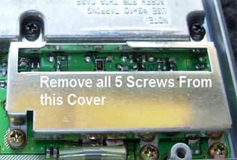
2. Before we begin the process, do not perform this modification unless you are good with a soldering iron and have knowledge of proper soldering techniques! Although this modification works and will give you an outstanding performing radio on 900MHz please note that you are performing this modification at your own risk. Remove the top and bottom covers of the radio along with the metal RF shield (5 screws), not to be confused with the VCO cover.
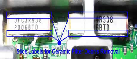
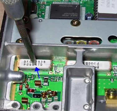
3. Using an X-ACTO knife or small razor blade slice the top of the labels on the existing 938MHz filters- this will ease removal of the insides of the filters. I remove the original filters by breaking them up carefully and removing the leftovers. I have done over 150+ radios and never had any mishaps, if you take your time and be cautious there’s nothing to lose sleep over! If you prefer you can remove the old filters by using a solder vacuum pump or solder wick. Either way it’s all about whatever you feel comfortable with.
4. Using a small Phillip’s head screwdriver, scribe, etc. insert it in the center of the 3-pole filter
5. Gently, but firmly, break the filter apart by moving the tool back and forth parallel to the front of the radio- remove debris as necessary using needle-nose pliers to remove the loose pieces of ceramic filter material. Use caution in doing this to insure the input and output terminals are left intact.
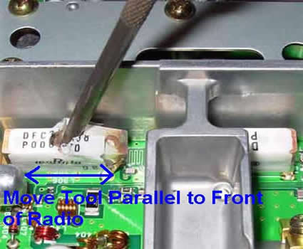
6. Repeat this process by inserting the tool in the center hole of the 4-pole filter and moving to the other 2 holes in this filter. Turn radio upside down and ensure all the debris are thoroughly removed- use needle nose pliers to once again remove the little pieces of ceramic filter material. Use caution to leave the input and output terminals intact.
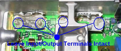
7. Using a pencil-tip 40-50 Watt soldering iron and small pliers, lay the radio on it’s side and gently pull on the filter input and output terminals from one side of the radio while touching their base with the soldering iron from the solder side of the main board- remove all 4 terminals. Each terminal should take around 2 seconds to remove. Use caution not to damage or overheat any SMD capacitors located near the terminals! Next is to remove the filter housings from the board. Using a pair of small needle-nose pliers and positioning the radio on its side, touch the base of the each housing with the soldering iron and put tension on the empty filter housing with the needle-nose pliers. Work from one end of each filter until the entire filter housing has been removed- take your time and be careful not to damage any of the surrounding areas of the board.
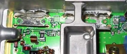
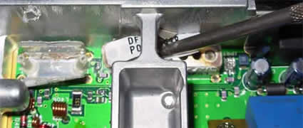
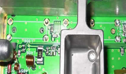
8. Using either a solder vacuum pump or solder wick remove all remaining solder from thru-holes on board. Please note if you are going to be using SMD type 915MHz filters, removal of solder from the ground terminal thru-holes is not necessary- just the input and output terminals are necessary.
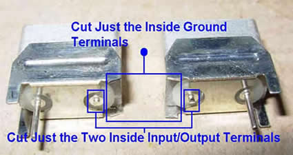
9. The next step is to assemble the 4 pole filter, others have different methods of doing this, presented here is the method I use. If you are going to use two 2-pole thru-hole style filters to make a 4-pole filter remove both the stickers from around the filters. Lay the filters side-by-side. One filter at a time using a small, sharp, pair of dykes cut flush the two pairs of ground terminals off of the inside of each filter. Then cut flush (as close to the filter body as possible) the inside terminals of each filter (the output terminal of one filter will be connected to the input terminal of the other).
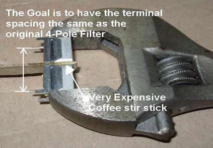
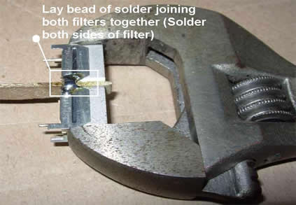
10. To join the filters together I use a Crescent wrench to hold them in place and a coffee stir stick, thin piece of cardboard, or just about anything as a spacer. The purpose of the spacer is so the filters will just drop into place in the original 4-pole location. You can use the bottom of the radio (solder side) as a guide on getting the spacing just right. Lay a bead of solder across each filter joining both filters together.
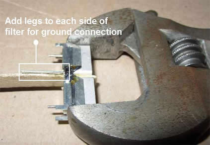
11. The filters have been joined together and as good measure I attach additional ground leads. I make grounding legs from old resistor leads- use whatever you have laying around. Ground legs should be placed on both sides of the 4-pole filter.
12. Now that the filters have been bonded together we must join their input/output terminals together. Lay a small bead on each terminal and connect together using a small leftover resistor lead or whatever you have laying around.
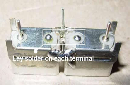
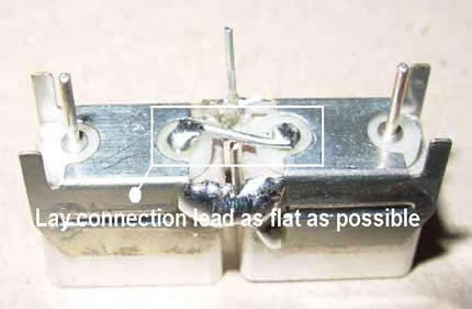
13. As an extra precaution I always add a small slice of electrical tape under the filter where the input/output terminals rest.
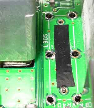
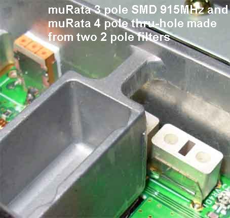
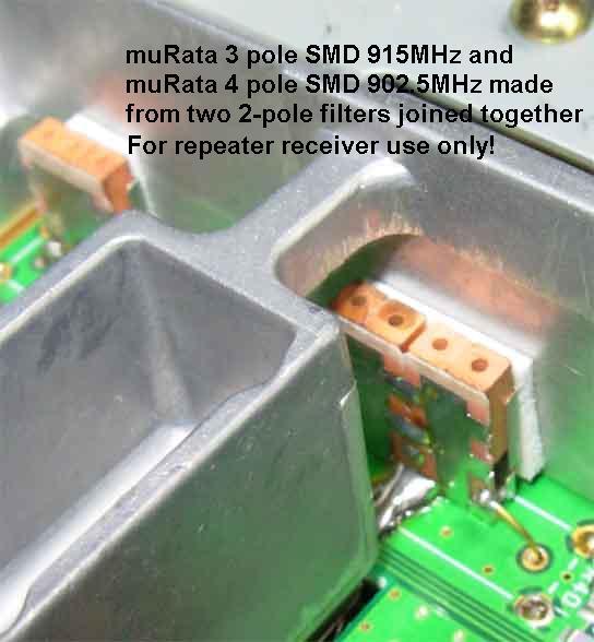
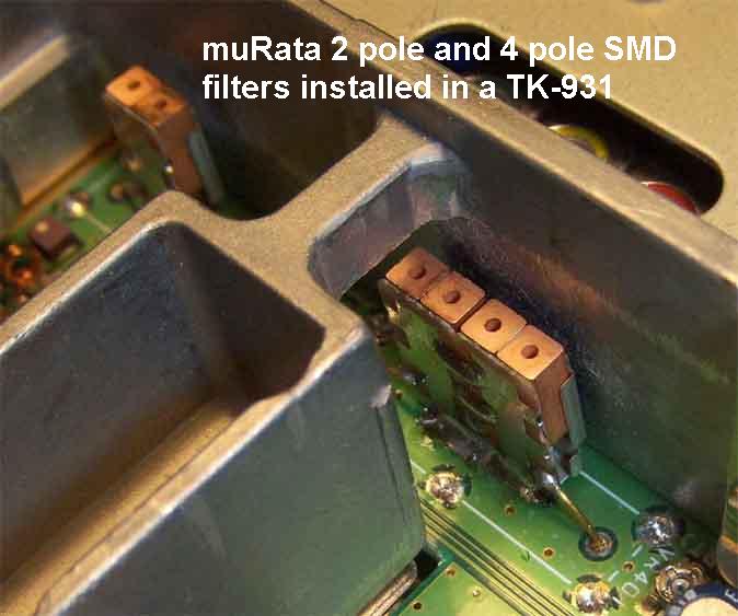
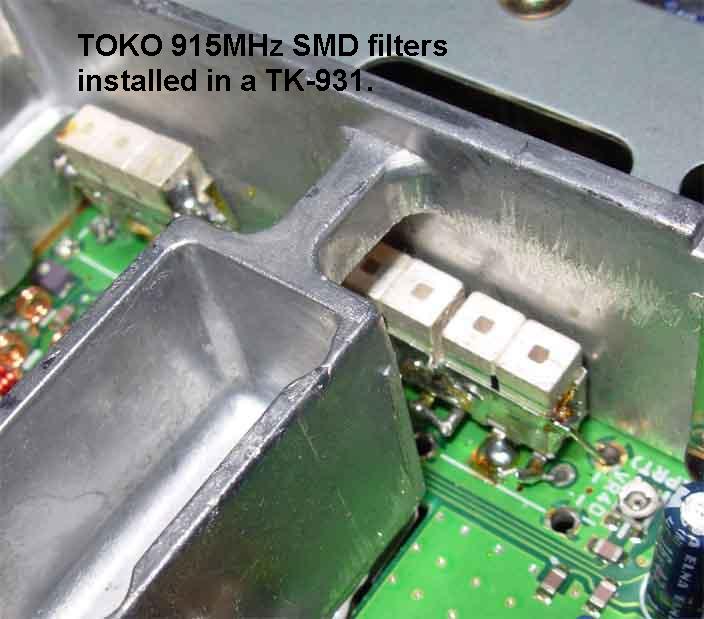
2. Presented here are completed filter installations using several different types of filters.